Introduction
AXIOLINE devices can be controlled from RTE 34.18.9.
Up to 63 I/O modules can be managed with motion control.
For their configuration use from project window tab configuration --> settings --> hardware.
The modules have retentive parameterization. It is a good idea to initialize them at every switch on so that, in case of module replacement, you have a correct configuration.
The status of the inputs is read at the same moment the channel is accessed. The status of the outputs is refreshed, if not "overridden" by bit 24 of SYS_CFG, at the system frequency.
NOTE: To get more diagnostic regarding the status and any alarms present, use the mreport command.
Bookmarks
Related arguments
Configuration of modules via Axiobus
Connection via Axiobus is only possible for RP-X motion controllers.
From the RDE project, open "Configuration" --> "Hardware", enter the device used (e.g. RP1), then select the "Axioline Modules" folder, press the INS key and enter the modules connected via AXIOLINE in order from the closest to the control to the farthest (these modules will all have Robox ID: r.id=0).
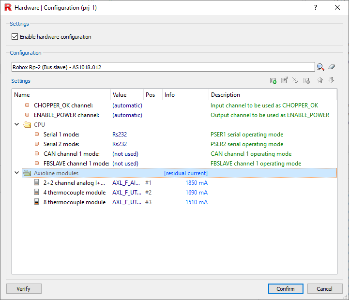
NOTE: The number found in the "Pos" column is equivalent to the slot assigned to the module, and which is needed (as is the r.id) to be able to use the functions/directions related to AXIO modules.
Press twice on each inserted Axioline module to add the additional requested parameters. For most axioline modules, the only parameter available is module I/O addressing (see below).
Addressing modules
When an Axioline module is inserted, a certain number of input words and output words are associated with it.
NOTE: See individual axioline modules in detail to understand better what the input/output words associated with it are used for.
The words associated with the module are set by the hardware configurator by pressing twice on each Axioline module entered. If a number is entered, the associated words will start from it; otherwise, if automatic, RTE will set the addressing.
In addition, regardless of the module entered, 16 input and output words are allocated for the axioline driver. Specifically, the first 4 input words will contain:
•BUS STATE: Contains the same value as the "diagnostic status register". Below is the table of the relative meaning of the bits:
Bit |
Designation |
Meaning |
|
|---|---|---|---|
0 |
F_PW_BIT |
I/O warning |
At least one device indicates "I/O warning" |
1 |
F_PF_BIT |
I/O error |
At least one device indicates "I/O error" |
2 |
F_BUS_BIT |
Bus error |
An error occurred on the bus |
3 |
F_CTRL_BIT |
Controller error |
The driver has detected an internal error |
4 |
- |
- |
Reserved |
5 |
F_RUN_BIT |
Run |
Data cycles have been exchanged, output data is enabled |
6 |
F-ACTIVE_BIT |
Active |
Configuration active, device PDI possible, data exchange with invalid/disabled process data |
7 |
F_READY_BIT |
Ready |
Local bus master is ready for operation, no data exchange off bus |
8 |
F_BD_BIT |
Bus different |
A device not belonging to the current configuration was detected in the last interface |
9 |
F_BASP_BIT |
SYS_FAIL |
The controller is in a stopped state or no application programs have been loaded. Output is locked (replacement value is active) |
10 |
F_FORCE_BIT |
Force mode |
Forcing mode active (startup tool/control I/O). |
11 |
F_SYNC_BIT |
Synchronization |
Synchronization between higher-level system and local bus master has failed |
12 |
F_PARA_REQ |
Module parameter |
At least one device requires parameters |
13 |
- |
- |
Reserved |
14 |
- |
- |
Reserved |
15 |
- |
- |
Reserved |
•DIAGNOSTIC PARAMETERS: Contains the code for any error present in one of the Axioline modules. The meaning of the error code can be found in the data sheet of the relevant module, or in the manual "UM EN AXL F SYS DIAG," which can be downloaded from the Phoenix Contact website
•ADDITIONAL INFO: Indicates the location of the module in question
•DEVICE COUNT: Indicates the number of Axioline modules present
NOTE: SAFETY modules are not considered.
There are two methods to figure out module addressing:
•Read the RHW.CFG file (simplest method), where there is a list of all input and output words used by the control, the Axioline module to which they are associated, and a description of their contents
•Use from task the GET_HW_INFO instruction (method to use if you want to manage everything by design)
Example
We have an RP-1 control with connected via Axioline these modules (from nearest to farthest): First module: AXL_F_DO64_1_2F module 64 digital output channels, occupies 4 words Second module: AXL_F_AI2_AO2_1H module 2+2 analog I/O channels, occupies 2 words Third module: AXL_F_DI_16_1_1H 1 module 16 digital input channels, occupies 1 word
Then the words will be arranged as follows: RP-1: OUT_W 1 -:- 19, INP_W 1 -:- 19 Axl_driver: OUT_W 20 -:- 35, INP_W 20 -:- 35 First module: OUT_W 36 -:- 39, INP_W 36 -:- 39 (even if inputs will not be used) Second module: OUT_W 40 -:- 41, INP_W 40 -:- 41 Third module: OUT_W 42, INP_W 42 (even if outputs will not be used) |
Configuration of modules via EtherCAT
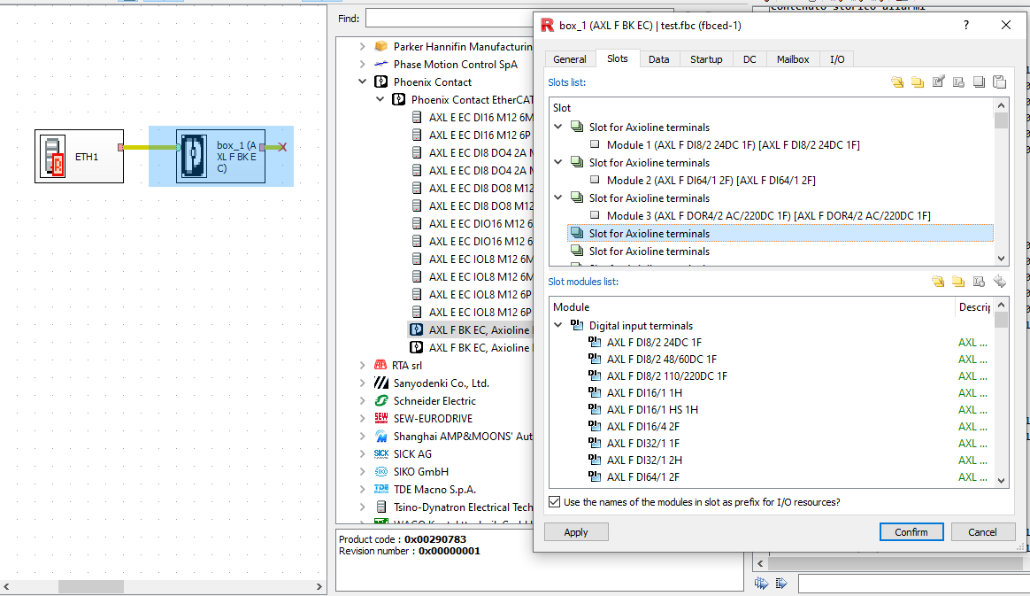
In order to operate connected via EtherCAT line, axiolines need the AXL_F_BK_EC module.
Enter the AXL_F_BK_EC module on the EtherCAT line, double click on it and under "slots" enter the next connected Axio modules. In this case the module marked "Module 1" will have slot 1 associated with it, the one with "Module 2" will have slot 2, and so on..
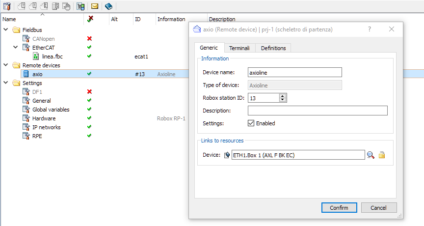
Generated the EtherCAT configuration, go back to the project configuration and press right mouse button, "New" --> "Remote Device..." --> "Axioline", then set all parameters in Generic, Terminals and Definitions.
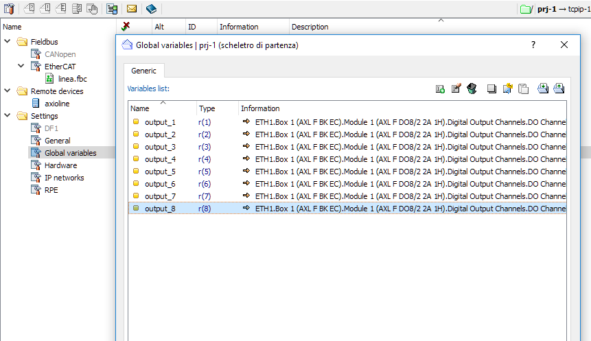
Select "Global variables" to associate the variables contained in the PDOs with the variables in the axis control (global variables).
NOTE: For more information on creating an EtherCAT line, press here.
Configuration of modules via Ethernet (Modbus/TCP)
In order to operate connected via Ethernet line communicating via Modbus/TCP, axiolines need the module AXL_F_BK_ETH.
For configuration, it is sufficient to have the PCMBC.CFG file in the flash.
Modules that communicate via Modbus/TCP should be parameterized through Modbus client commands, and not using AXIO_ROBJ and AXIO_WOBJ.
NOTE: Not all axioline modules can be used with this configuration, to see the available modules, see the PCMBC.CFG file.
Device commands and functions available
These commands and functions can also be used if devices are connected on the EtherCAT line via the AXL_F_BK_EC bus coupler.
Available commands (usable from shell and STP file):
Directive to read objects on Axioline fieldbus |
|
Directive to write objects to Axioline fieldbus |
Available functions (usable by program):
AXIO_ROBJ |
Function to read objects on Axioline fieldbus |
AXIO_WOBJ |
Function to write objects to Axioline fieldbus |
Functions for IOlink master (AXL_SE_IOL4) (unmanaged IOLink configurator):
AXIO_IOL_R |
Function to read a data area from known IOlink master |
AXIO_IOL_W |
Function to write a data area to known IOlink master |
Other available commands and functions:
Directive to enable exclusive rights of axioline modules |
|
AXIO_PM_R |
Function to read a data area from module AXL_F_PM_EF_1F |
Directive to update fw of RO-AXIO_SE_STP2 modules |
Keywords Axioline
SYS_FLAG.18 |
Enable diagnostic report on asynchronous reading of internal Axioline objects |
|---|---|
SYS_CFG_2.20 |
Sets the active mode of the local Axioline bus when the operating mode is changed to loading |
SYS_CFG_2.23 |
Input and output areas of AXL_F_BK_ETH (PCMBC) are no longer updated when in loading mode. The values of the physical outputs set when the control is in loading mode depend on the configuration of the various devices |
Defines a remote AXL_SE_IOL4 device connected to an AXL_F_BK_EC |
|
Defines one or more AXL_F_PM_EF_1F terminals on ECAT device |
Axioline module list
The table lists all modules that can be used via Axioline that can be managed via RDE project.
NOTE: There are no SAFETY modules in the list, as they are configured differently.
Modules |
Description |
Input Word |
Word Output |
|---|---|---|---|
Digital inputs: |
|
|
|
16-channels digital input module |
1 |
0 |
|
16-channels digital input module |
1 |
0 |
|
16-channels digital input module |
1 |
0 |
|
32-channels digital input module |
2 |
0 |
|
32-channels digital input module |
2 |
0 |
|
64-channels digital input module |
4 |
0 |
|
|
|
|
|
Digital outputs: |
|
|
|
4 channels digital output module |
0 |
1 |
|
8-channels digital output module |
0 |
1 |
|
16-channels digital output module |
0 |
1 |
|
16-channels digital output module |
0 |
1 |
|
16-channels digital output module |
0 |
1 |
|
32-channels digital output module |
0 |
2 |
|
64-channels digital output module |
0 |
4 |
|
|
|
|
|
Digital I/O: |
|
|
|
8+8 digital I/O channels module |
1 |
1 |
|
8+8 digital I/O channels module |
1 |
1 |
|
16+8 digital I/O channels module |
1 |
1 |
|
16+16 digital I/O channels module |
1 |
1 |
|
|
|
|
|
Analog inputs: |
|
|
|
4-channels analog input module(I) |
4 |
0 |
|
4-channels analog input module(V) |
4 |
0 |
|
8-channels analog input module |
8 |
0 |
|
|
|
|
|
Analog outputs: |
|
|
|
4-channels analog output module |
4 |
4 |
|
8-channels analog output module |
8 |
8 |
|
|
|
|
|
Analog I/O: |
|
|
|
2+2 analog I/O channels module |
2 |
2 |
|
|
|
|
|
Thermocouples: |
|
|
|
4 thermocouples module |
5 |
1 |
|
8 thermocouples module |
9 |
1 |
|
|
|
|
|
Thermoresistences: |
|
|
|
4 thermoresistences module |
4 |
0 |
|
8 thermoresistences module |
8 |
0 |
|
8 thermoresistences module |
8 |
0 |
|
|
|
|
|
Miscellaneous: |
|
|
|
module 2 counters / 2 incremental encoders |
14 |
14 |
|
4 relay outputs module |
0 |
1 |
|
power measurement module |
0 |
0 |
|
module 2 PWM outputs |
0 |
4 |
|
module for serial communication |
6 |
0 |
|
module for reading 2 load cells |
6 |
2 |
|
SSI interface module for absolute encoder |
6 |
6 |
|
SE Series: |
|
|
|
4-channels analog input module(I) |
4 |
0 |
|
4-channels analog input module(V) |
4 |
0 |
|
4-channels analog output module(I) |
4 |
4 |
|
4-channels analog output module(V) |
4 |
4 |
|
4-channel analog output module (V) |
4 |
4 |
|
counter module |
3 |
3 |
|
16-channels digital input module |
1 |
0 |
|
16-channels digital input NPN module |
1 |
0 |
|
16-channels digital output module |
0 |
1 |
|
16-channels digital output NPN module |
0 |
1 |
|
2 relay outputs module |
0 |
1 |
|
incremental encoder module |
5 |
1 |
|
IO-link master module |
3 |
1 |
|
RS232 serial communication module |
0 |
0 |
|
RS485 serial communication module |
0 |
0 |
|
4 PT100 thermoresistances module |
4 |
0 |
|
cover module |
0 |
0 |
|
4 thermocouples/linear voltages module |
5 |
1 |
|
dual-channel stepper motor module |
0 |
0 |