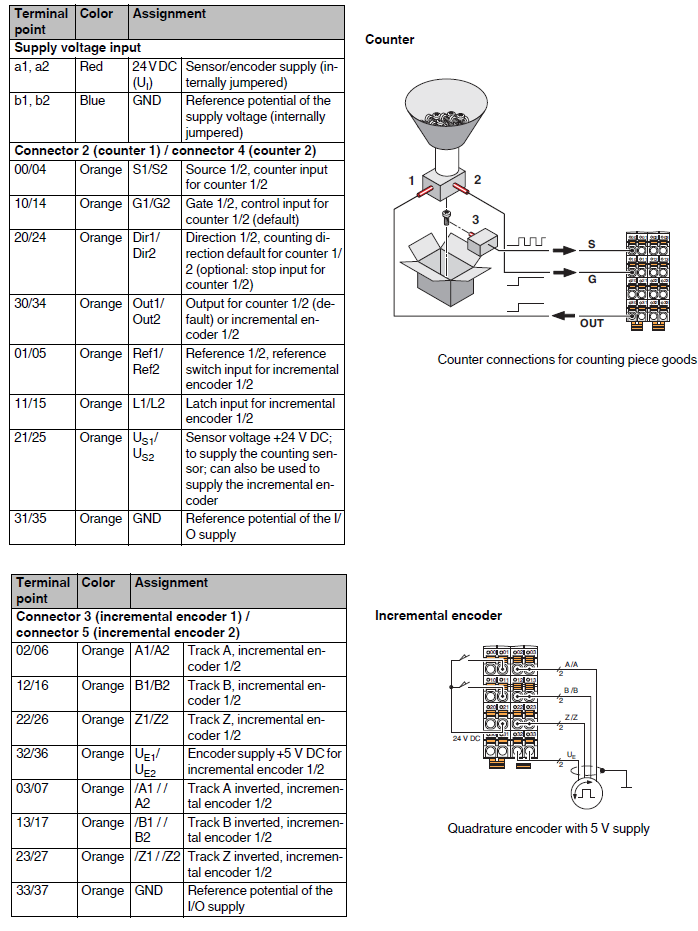
Axioline F function module, 2 counting inputs, 2 incremental encoder inputs.
COUNTER channels have two physical inputs (source 1 for channel 1, source 2 for channel 2) through which counting is performed. The maximum signal frequency is 300kHz if only one channel is used, or 100kHz if both are used.
The control part of the counter covers:
•The START/STOP of the count (gate 1 for channel 1, gate 2 for channel 2).
•The direction of the count (direction 1 for channel 1, direction 2 for channel 2), that is, if the count increases or decreases. Optionally they also have stop input function.
•Two outputs (out 1 for channel 1, out 2 for channel 2) used to indicate when the limit (minimum or maximum) of the count is reached. These outputs are shared with the encoder channels (out 1 can be used by counter channel 1 or encoder channel 1 but not both, same for out 2).
INCREMENTAL ENCODER channels have six physical inputs (track A+, B+, Z+, A-, B-, Z-) used for incremental encoder readout. The maximum signal frequency is 300kHz if only one channel is used, or 100kHz if both are used.
The control part of the encoder covers:
•The reference signal (reference 1 for channel 1, reference 2 for channel 2) used to determine the encoder position.
•The latch signal (latch 1 for channel 1, latch 2 for channel 2) used to store the encoder quota and send it to the control.
•Two outputs (out 1 for channel 1, out 2 for channel 2) used to indicate when the maximum quota or minimum quota has been reached. These outputs are shared with the counter channels (out 1 can be used by counter channel 1 or encoder channel 1 but not both, same for out 2).
WARNING: Both the counter (gate, dir, out) and encoder (ref, latch, out) control parts can be managed in two ways: Through signals external to the module (see "Connections"), in which case parameterization of these signals must be done through Application object 0X80; or through the INPUT WORDs and OUTPUT WORDs associated with the module. The former method has higher priority than the latter, i.e., the values present on the input/output words are significant only for certain values of the 0x80 object (see input/output word).
Note: Since RTE 34.24.6, handling of this axioline module as a possible incremental encoder type transducer has been integrated. Unfortunately, neither picture nor homing of precise type is possible. As u0 the input of Reference is used.
NOTE: Only some information in the module data sheet is given below. For more details refer to the data sheet itself.
Connections
Input/Output Word
The module is allocated 14 INPUT WORD and 14 OUTPUT WORD:
Some input/output words are valid only according to a certain parameterization of Application Object 0X80.
NOTE: Input and output words 0 and 1 are used for both the two channels, depending on the bit I am going to consider.
Output words
Output words |
BIT for ch. 1 |
BIT for ch. 2 |
Content |
Description |
|---|---|---|---|---|
0 |
8 |
0 |
Start CNT |
= 1: counter running (valid only if Stop CNT = 0) Valid only if Appl. obj. 0x80 has gate mode = "gate off" |
9 |
1 |
Stop CNT |
= 1: counter stopped (dominant bit over Start CNT) Valid only if Appl. obj. 0x80 has: Gate mode = "gate off," "Start count with rising edge," or "Start count with falling edge." Direction/stop mode = "No function" or "change direction on rising/descending edge (start direction is to increment/decrement) |
|
10 |
2 |
Dir CNT |
= 1: increments the count = 0: decreases the count Valid only if Appl. obj. 0x80 has Direction/stop mode = "No function" or "increments if high/low level" |
|
11 |
3 |
Reset CNT |
= 1: The count is reset and the starting value is reloaded |
|
12 |
4 |
Set OUT |
= 1: output set high = 0: output set low Valid only if Appl. obj. 0x80 has Output mode = "output set by control" |
|
13 |
5 |
SetNewLimits |
0->1: The limits specified through "process data" have been transferred |
|
1 |
8 |
0 |
SetRef INC |
0->1: The Encoder Channel Reference is imposed immediately. Valid only if Appl. obj. 0x80 has Reference Type = "set directly from control" |
9 |
1 |
EnableRef INC |
0->1: Start of encoder channel reference lookup phase. Valid only if Appl. obj. 0x80 has Reference Type other than "set directly from control" |
|
2 |
High word of the lower limit of CNT1 |
|||
3 |
Word low of the lower limit of CNT1 |
|||
4 |
Word high of the upper limit of CNT1 |
|||
5 |
Word low of the upper limit of CNT1 |
|||
6 |
Word high of the lower limit of CNT2 |
|||
7 |
Word low of the lower limit of CNT2 |
|||
8 |
Word high of the upper limit of CNT2 |
|||
9 |
Word low of the upper limit of CNT2 |
|||
10..13 |
Reserved |
|||
Input words
Input words |
BIT for ch. 1 |
BIT for ch. 2 |
Content |
Description |
|---|---|---|---|---|
0 |
8 |
0 |
Run/Stop CNT |
= 1: counter running = 0: counter stopped |
9 |
1 |
Dir CNT |
= 1: increments the count = 0: decreases the count |
|
10 |
2 |
Gate CNT |
= 1: gate input, high state = 0: gate input, low state |
|
11 |
3 |
Dir/Stop Input CNT |
= 1: Dir/StopInput, high state = 0: Dir/StopInput, low state |
|
12 |
4 |
OUT |
= 1: Output, high state = 0: Output, low state |
|
13 |
5 |
Limit Conf CNT |
= 1: The new counter limit value was successfully transferred |
|
14 |
6 |
Reserved |
Leave at 0 |
|
15 |
7 |
Error CNT |
= 1: Error on the CNT channel = 0: No error |
|
1 |
8 |
0 |
Run/Stop INC |
= 1: encoder rotating = 0: encoder stopped |
9 |
1 |
Dir INC |
= 1: positive encoder rotation = 0: negative rotation of the encoder |
|
10 |
2 |
EncSurv INC |
= 1: Error on encoder status monitored by firmware = 0: No error Valid only if Appl. obj. 0x80 has Encoder monitoring ON |
|
11 |
3 |
Latch INC |
= 1: High state of the Latch input = 0: Low state of the Latch input |
|
12 |
4 |
RunRef INC |
= 1: Reference search phase in progress = 0: Reference search phase not in progress |
|
13 |
5 |
RefCompl INC |
= 1: Reference search phase completed = 0: Reference search phase not completed |
|
14 |
6 |
StateRef INC |
= 1: Input for reference set = 0: Input for reference not set |
|
15 |
7 |
Error INC |
= 1: Error on channel INC = 0: No error |
|
2 |
High word of the status counter of CNT1 |
|||
3 |
Word low of the status counter of CNT1 |
|||
4 |
Word high of the status counter of CNT2 |
|||
5 |
Word low of the status counter of CNT2 |
|||
6 |
Word high of the position of INC1 |
|||
7 |
Low word of the position of INC1 |
|||
8 |
Word high of the "latch value" of INC1 |
|||
9 |
Low word of the "latch value" of INC1 |
|||
10 |
Word high of the position of INC2 |
|||
11 |
Low word of the position of INC2 |
|||
12 |
Low word of the "latch value" of INC2 |
|||
13 |
Low word of the "latch value" of INC2 |
|||
Parameterization
Name |
Description |
Index |
R/W |
Subindex |
Type |
Length |
Content |
|---|---|---|---|---|---|---|---|
Para Table |
Contains in its subindexes the words for parameterization of CNT and INC channels. |
0x0080
|
R/W |
0 |
Record |
176 |
Reads/writes all elements |
1 |
Record |
44 |
Parameterization of CNT1 |
||||
2 |
Record |
44 |
Parameterization of CNT2 |
||||
3 |
Record |
44 |
Parameterization of INC1 |
||||
4 |
Record |
44 |
Parameterization of INC2 |
Parameterization of CNT
The table lists all the elements (each with its own data type, since we are talking about a record) of which the objects 0x80 sub 1 and sub 2 are composed.
Variable |
Type |
Content |
BIT |
Value |
|---|---|---|---|---|
Basic Config |
U16 |
Counting method |
0..3 |
0x1 Periodic (default) |
0x0 One-time |
||||
+ |
||||
Gate mode, parameterizes the gate signal if it is taken external to the module |
4..7 |
0x00 Gate OFF |
||
0x10 Count on high level |
||||
0x20 Count on low level |
||||
0x30 Start counting on rising edge |
||||
0x40 Start counting on falling edge |
||||
0x50 Count on high level and reset count on rising edge |
||||
0x50 Count on low level and reset count on falling edge |
||||
+ |
||||
Direction/stop input mode, parameterizes the direction signal if it is taken external to the module |
8..11 |
0x000 Not used |
||
0x100 Change direction on rising edge (start direction is to increment) |
||||
0x200 Changes direction on rising edge (start direction is to decrement) |
||||
0x300 Changes direction on falling edge (start direction is to increment) |
||||
0x400 Change direction on falling edge (start direction is to decrement) |
||||
0x500 Increment on high signal |
||||
0x600 Increment on low signal |
||||
0x700 Stop on rising edge |
||||
0x800 Stop on falling edge |
||||
Reserved |
U16 |
Reserved |
|
|
Output Config |
U16 |
Output mode, parameterizes the signal out |
0..3 |
0x0 Output disabled for this channel (default) |
0x1 Output set high if limit value is reached (starts from low state) |
||||
0x2 Output set low if limit value is reached (starts from high state) |
||||
0x3 Output changes state whenever limit value is reached (starts from low state) |
||||
0x4 Output changes state whenever limit value is reached (starts from high state) |
||||
0x5 The output generates a parameterizable high pulse between 1ms and 1s whenever the limit value is reached |
||||
0x6 Output generates a parameterizable low pulse between 1ms and 1s whenever the limit value is reached |
||||
0x7 The output is set by the control |
||||
+ |
||||
Output mode, sets the limits for which out is used |
4..7 |
0x00 Output not used (default) |
||
0x10 Lower limit |
||||
0x20 Upper limit |
||||
0x30 Both limits |
||||
Output pulse time |
U16 |
Out pulse duration in milliseconds |
Value between 1 (default) and 1000 |
|
Start Value |
U32 |
Start Value |
Value between 0 (default) and 429496729 |
|
Lower Limit |
U32 |
Lower Limit |
Value between 0 (default) and 429496729 |
|
Upper Limit |
U32 |
Upper Limit |
Value between 0 and 429496729 (default) |
|
Reserved |
U32 |
Reserved |
0 (default) |
|
Reserved |
U32 |
Reserved |
0 (default) |
|
Reserved |
U32 |
Reserved |
0 (default) |
|
Reserved |
U32 |
Reserved |
0 (default) |
|
Reserved |
U32 |
Reserved |
0 (default) |
|
Reserved |
U32 |
Reserved |
0 (default) |
|
Parameterization of INC.
The table lists all the elements (each with its own data type, since we are talking about a record) of which 0x80 sub 3 and sub 4 objects are composed.
Variable |
Type |
Content |
BIT |
Value |
|---|---|---|---|---|
Basic Config |
U16 |
Channel Enable |
0 |
0x0 Not active (default) |
0x1 Active |
||||
+ |
||||
Axis type |
1 |
0x0 Linear (default) |
||
0x2 Rotational |
||||
+ |
||||
Encoder type |
2 |
0x0 Symmetrical (default) |
||
0x4 Asymmetrical |
||||
+ |
||||
Z signal |
4 |
0x00 Encoder without Z signal (default) |
||
0x10 Encoder with Z signal |
||||
+ |
||||
Encoder monitoring |
5 |
0x00 OFF (default) |
||
0x20 ON |
||||
+ |
||||
Latch input mode, parameterizes the latch signal if it is used external to the module |
6..7 |
0x00 OFF (default) |
||
0x40 Positive edge |
||||
0x80 Negative edge |
||||
0xC0 Both edges |
||||
+ |
||||
Counting method |
8..9 |
0x000 Reserved |
||
0x100 Reserved |
||||
0x200 Double: the rising edges of both signals A and B are detected. |
||||
0x300 Quadruple: both edges of both signals are detected (default) |
||||
+ |
||||
Reference type, parameterizes the reference signal if it is taken external to the module |
12..15 |
0x0000 Reference set directly from control (default) |
||
0x1000 Reference taken on the high edge of the reference signal, with positive encoder signal direction |
||||
0x2000 Reference taken on the high edge of the reference signal, with negative encoder signal direction |
||||
0x3000 Reference taken on the low edge of the reference signal, with positive encoder signal direction |
||||
0x4000 Reference taken on the low edge of the reference signal, with negative encoder signal direction |
||||
0x5000 Reference taken on the high edge of the reference signal, with positive direction, using the Z signal |
||||
0x6000 Reference taken on the high edge of the reference signal, with negative direction, using the Z signal |
||||
0x7000 Reference taken on the low edge of the reference signal, with positive direction, using the Z signal |
||||
0x8000 Reference taken on the low edge of the reference signal, with negative direction, using Z signal |
||||
0x9000 Reference using Z |
||||
Reserved |
U16 |
Reserved |
|
|
Output Config |
U16 |
Output mode, parameterizes the out signal if it is taken external to the module |
0..2 |
0x0 Output disabled for this channel (default) |
0x1 Output set high if limit value is reached (starts from low state) |
||||
0x2 Output set low if limit value is reached (starts from high state) |
||||
0x3 Output changes state whenever limit value is reached (starts from low state) |
||||
0x4 Output changes state whenever limit value is reached (starts from high state) |
||||
0x5 The output generates a parameterizable high pulse between 1ms and 1s whenever the limit value is reached |
||||
0x6 Output generates a parameterizable low pulse between 1ms and 1s whenever the limit value is reached |
||||
0x7 The output is set by the control |
||||
+ |
||||
Output mode, sets the limits for which the output is used out |
4..5 |
0x00 Output not used (default) |
||
0x10 Lower limit |
||||
0x20 Upper limit |
||||
0x30 Both limits |
||||
Output pulse time |
U16 |
Out pulse duration in milliseconds |
Value between 1 (default) and 1000 |
|
Conv Fact |
U32 |
Gear Ratio, indicates how many units correspond to a certain number of increments |
Bits 0..15 indicate the denominator |
|
Bits 16..31 indicate the numerator |
||||
ModuloVal |
U32 |
For rotary axes, indicates the length (path) of an entire axis revolution |
Value between 1 (default) and 429496729 |
|
EncIncVal |
U32 |
Encoder increment value |
Value between 0 (default) and 107374182 |
|
1LimitValOut |
U32 |
First limit relative to the out signal. For the rotary axis make sure that 1LimitValOut =< ModuloVal |
Value between 0 (default) and 429496729 |
|
2LimitValOut
|
U32 |
Second limit relative to the signal out. For the rotary axis make sure that 2LimitValOut =< ModuloVal |
Value between 0 and 429496729 (default) |
|
ReferenceVal |
U32 |
Reference value |
Value between 0 (default) and 429496729 |
|
OffsetZRef |
U32 |
Offset between the reference and the Z signal detection used to set the reference |
Value between 0 (default) and 429496729 |
|
TransmFact |
U32 |
Gear ratio for rotary axes |
Value between 1 (default) and 429496729 |
|
Reserved |
U32 |
Reserved |
0 (default) |
|