Axioline F, Analog input/output module, Analog inputs: 2, 0V..5V, -5V..5V, 0V..10V, -10V..10V, 0mA..20mA, 4mA..20mA, -20mA..20mA, Connection technique: 2 conductors, Analog outputs: 2, 0V..5V, -5V..5V, 0V..10V, -10V..10V, 0mA..20mA, 4mA..20mA, -20mA..20mA, Connection technique: 2-conductor, Transmission rate in the local bus 100 MBit/s, IP20 degree of protection.
NOTE: Only some information in the module data sheet is given below. For more details refer to the data sheet itself.
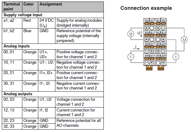
Connections
Input/Output Word
At he module are allocated 2 INPUT WORD and 2 OUTPUT WORD:
Each INP_W corresponds to an analog input.
Each OUT_W corresponds to an analog output.
Parameterization
Name |
Description |
Index |
R/W |
Subindex |
Type |
Lenght (Bytes) |
Content |
|---|---|---|---|---|---|---|---|
Para Table |
Contains in its sub-indexes the words for each channel's and data format parameterization |
0x0080 |
R/W |
0 |
Array of Unsigned 16 |
6 * 2 |
Reads/writes all elements |
1 |
Unsigned 16 |
2 |
"Parameterization word" of INP channel 1 (default 0x0) |
||||
2 |
Unsigned 16 |
2 |
"Parameterization word" of INP channel 2 (default 0x0) |
||||
3 |
Unsigned 16 |
2 |
"Parameterization word" of the OUT 1 channel (default 0x0) |
||||
4 |
Unsigned 16 |
2 |
"Parameterization word" of OUT 2 channel (default 0x0) |
||||
5 |
Unsigned 16 |
2 |
"Data Format" (default 0x0) |
||||
6 |
Unsigned 16 |
2 |
Reserved (default 0x0) |
Parameterization word (input)
Parameter |
BIT |
Value |
Configuration |
|---|---|---|---|
Measuring range |
0..3 |
0x0 |
0V .. 10V (default) |
0x1 |
±10V |
||
0x2 |
0V .. 5V |
||
0x3 |
±5V |
||
0x4 |
0mA ... 20mA |
||
0x5 |
±20mA |
||
0x6 |
4mA ... 20mA |
||
0x7 .. 0xE |
Reserved |
||
0xF |
Channel not active |
||
+ |
|||
Average value |
8..9 |
0x000 |
16 samples (default) |
0x100 |
No average value |
||
0x200 |
4 samples |
||
0x300 |
32 samples |
||
+ |
|||
Input filter |
12 |
0x0000 |
30 Hz (default) |
0x1000 |
12 kHz |
||
Parameterization word (output)
Parameter |
BIT |
Value |
Configuration |
|---|---|---|---|
Measurement range |
0..3 |
0x0 |
0V .. 10V (default) |
0x1 |
±10V |
||
0x2 |
0V .. 5V |
||
0x3 |
±5V |
||
0x4 |
0mA ... 20mA |
||
0x5 |
±20mA |
||
0x6 |
4mA ... 20mA |
||
0x7 .. 0xE |
Reserved |
||
0xF |
Channel not active |
Data format
The data format indicates how the measurement values (voltage/current/temperature) read/write by Axio modules are represented (in the input/output words of the control).
NOTE: For representation of values outside the range of the scale used, refer to the module's own documentation.
All word values in the table under the description column are in decimal format.
Configuration |
Value |
Description |
|---|---|---|
IB IL (default) |
0x000 |
The upper word full scale value equals +30000, and the lower word full scale value equals 0 if I have positive range only, otherwise -30000. The unit value of the word equals: (positive range)/30000 |
Reserved |
0x100 |
|
S7 compatible |
0x200 |
The upper word unit value is equivalent to +27648, while the lower word unit value is equivalent to 0 if I have positive range only, otherwise -27648. The unit value of the word equals: (positive range)/27648 |
Standard Representation |
0x300 |
The value present on the words equals the input/output measurement measured in mV or mA |
Example
I want to configure input channel 2 of the axioline module (r.id 0 slot 1) as follows: Measurement range 4mA ... 20mA, average value with 32 samples, input filter of 12 kHz. The value of the Parameterization word will be: 0x6 + 0x300 + 0x1000 = 0x1306 To give the parameterization I use from shell the command AXIO_WOBJ: AXIO_WOBJ 0 1 0x80 2 0x1306 |
Example
I want to configure output channel 2 of axioline module (r.id 0 slot 1) with measurement range 4mA ... 20mA. The value of the Parameterization word will be: 0x06 To give the parameterization I use from shell the command AXIO_WOBJ: AXIO_WOBJ 0 1 0x80 4 0x06 |
Example
Data format IB IL Range ±10V, if I have the INP_W = -200 then I am reading: -200*(10/30000) = -66.666mV Range 4mA ... 20mA, if I impose OUT_W = 1 then I have output: (0.016/27648) + 0.004 = +4.0005333mA (for this range out_w =0 corresponds to 4mA) Data format S7 compatible Range 0V ... 5V, if I have the INP_W = 3 then I am reading: 3*(5/27648) = +542.5μV Range 0mA ... 20mA, if I impose OUT_W = 1 then I have output: (0.02/27648) = +0.7234μA Data format Standard representation If the INP_W of an analog channel is -12000 then I am reading -12mA If I impose the OUT_W of a digital channel equal to 9500 I get 9.5V at the output |