File used by the RTE manager to describe the hardware configuration used.
It must be in the alias folder HW_DIR or USER_DIR, otherwise alarm 988 is generated at switch on. RTE will look for the file in HW_DIR and, if not present, will switch to look for it in USER_DIR.
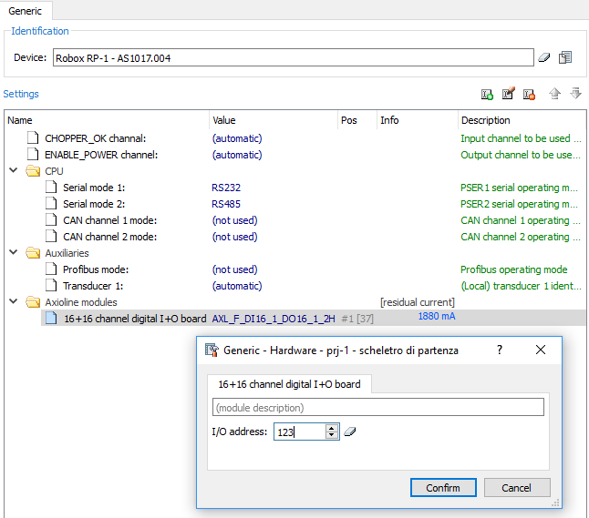
WARNING: This file is automatically generated based on the information entered in the Project Configurator -> Hardware (see Hardware Settings for more details).
The file is automatically placed in the "files in flash" table. Obviously it will need to be transferred to the CF of the connected motion controller so that it will be assumed at the next switch on.
NOTE: To enable this feature, the auto-generation option of the RHW.CFG file must be selected. From the project configurator, press on the properties icon (the first on the top left) -> Configuration -> Hardware.
NOTE: The AUTOCONFIG shell command is also available, which commands the control to create the RHW.CFG file automatically. The generated file will be placed in the HW_DIR folder.
NOTE: From RDE 3.51.0 it is possible to set the IW and OW addresses of the RP-1 expansion modules (limited to the first 256 words).
This file can also be self-generated by RTE in /f@/ (or in /fa/ in case /f@/ results to be full) following the AUTOCONFIG shell command.
 | List of supported Axioline modules in rhw.cfg |
|
Example
RHW.CFG file generated related to uRMC control (AS1017.001):
; ROBOX Cpu PN AS1017.001 - self created /F@/RHW.CFG file ; Date 08/07/08 Time 10:03:37 ; OSF Version Robox OSF_PPC OSF 32bit<V 13.12 > , BIOS Version 1.4.3 [MCPU] SLOT 0 CPURBX ; First Iw/Ow 1 ; PSER serial channels ; PSER n {RS232 | RS422 | RS485 | GUN} ; Fast Autoconfiguration PSER 1 RS232 PSER 2 RS485 ; replace RS485 with GUN, ; then upload the new rhw.cfg to the CF to connect Dispan/Vispan devices to SER2 ; ETH Ethernet channels ; ETH n ; n = eth interface (1 = main) ETH 1 ; CAN channels ; CAN n {CanOpen402 | Unused} CAN 1 CanOpen402 ; code=0x06 CAN 2 CanOpen402 ; code=0x06 ; replace CanOpen402 with Unused, ; then reload rhw.cfg to CF if CAN2 is not used to avoid alarm9204 ; PROFIBUS channels ; PROFIBUS n {DPS | Unused} PROFIBUS 1 DPS SLOT 1 AUX1_URMC ; First Iw/Ow 17 ; Input words map IW 1 SLOT 0.01 ; CPURBX (User Cpu keys) IW 2 SLOT 0.02 ; CPURBX (Cpu Jumpers) IW 3 SLOT 0.03 ; CPURBX (Robox RBXGUN keys #1) IW 4 SLOT 0.04 ; CPURBX (Robox RBXGUN Keys #2) IW 5 SLOT 0.05 ; CPURBX (Robox RBXPAN Keys #1) IW 6 SLOT 0.06 ; CPURBX (Robox RBXPAN Keys #2) IW 7 SLOT 0.07 ; CPURBX (Robox RBXPAN Keys #3) IW 8 SLOT 0.08 ; CPURBX (Robox DISPAN Keys #1) IW 9 SLOT 0.09 ; CPURBX (Robox DISPAN Keys #2) IW 10 SLOT 0.10 ; CPURBX (First 16 inp) IW 11 SLOT 0.11 ; CPURBX (Second 16 inp) IW 12 SLOT 0.12 ; CPURBX (Board Status) IW 13 SLOT 0.13 ; CPURBX (First 16 latched on Int.) IW 14 SLOT 0.14 ; CPURBX (Second 16 latched on Int.) IW 15 SLOT 0.15 ; CPURBX (Robox Reserved #1) IW 16 SLOT 0.16 ; CPURBX (Robox Reserved #2) IW 17 SLOT 1.01 ; AUX1_URMC (Real position #1) IW 18 SLOT 1.02 ; AUX1_URMC (Zero position #1) IW 19 SLOT 1.03 ; AUX1_URMC (Channel status #1) ; Output words map OW 1 SLOT 0.01 ; CPURBX (Display Leds) OW 2 SLOT 0.02 ; CPURBX (Cpu User Leds) OW 3 SLOT 0.03 ; CPURBX (Robox minigun leds) OW 4 SLOT 0.04 ; CPURBX (Robox RBXPAN Ascii key) OW 5 SLOT 0.05 ; CPURBX (Robox RBXPAN Edges #1) OW 6 SLOT 0.06 ; CPURBX (Robox RBXPAN Edges #2) OW 7 SLOT 0.07 ; CPURBX (Robox RBXPAN Edges #3) OW 8 SLOT 0.08 ; CPURBX (Robox DISPAN leds) OW 9 SLOT 0.09 ; CPURBX (Robox Reserved #1) OW 10 SLOT 0.10 ; CPURBX (First 16 out) OW 11 SLOT 0.11 ; CPURBX (Second 16 out) OW 12 SLOT 0.12 ; CPURBX (Robox Reserved #2) OW 13 SLOT 0.13 ; CPURBX (Robox Reserved #3) OW 14 SLOT 0.14 ; CPURBX (Robox Reserved #4) OW 15 SLOT 0.15 ; CPURBX (Robox Reserved #5) OW 16 SLOT 0.16 ; CPURBX (Robox Reserved #6) OW 17 SLOT 1.01 ; AUX1_URMC (Zero cycle kind #1) TRD 1 IW 17 CHOPPER_OK CH 152 ENABLE_POWER CH 152 PSER 2 GUN ; replace RS485 with GUN, then upload the new rhw.cfg to the CF to connect Dispan/Vispan devices to SER2 See RSW.CFG file for its configuration CAN 2 unused ; replace CanOpen402 with Unused, then reload rhw.cfg to CF if CAN2 is not used to avoid alarm9204 PROFIBUS 1 Unused ; replace DSP with Unused, then reload rhw.cfg to CF if PROFIBUS channel is not used to avoid alarm9200 Red buttons present on CPU (adv bit 0). See dispan_keys INP 1 = (10-1)*16 +1 = 145 LEDs present on CPU Numeric display (seven segments). OUT 1 = (10-1)*16 +1 = 145 Physical ENC on uRMC INP 8 : equals the index (0) default in the POWER SET OUT 8 : equals the index (0) predefined in the POWER SET |