Axioline F, Analog output module, Analog outputs: 8, 0V..5V, -5V..5V, 0V..10V, -10V..10V, 0mA..20mA, 4mA..20mA, -20mA..20mA, Connection technique: 2 conductors, Transmission rate in the local bus 100 MBit/s, IP20 degree of protection.
NOTE: Only some information in the module data sheet is given below. Please refer to the data sheet itself for more details.
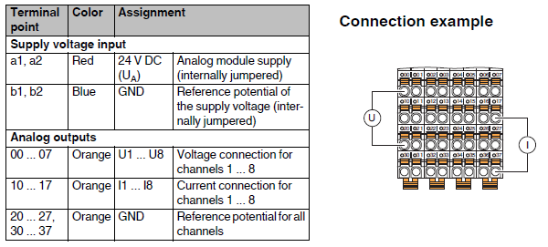
Connections
Input/Output Word
The module is allocated 8 INPUT WORD and 8 OUTPUT WORD:
Each OUT_W corresponds to an analog output.
The INP_W are used as diagnostics of the respective channel only in case of "IB IL" format, in case of S7 compatible format they are not used (see DATA FORMAT below). The values they can take are:
•0X8002 Open circuit
•0X8003 Short-circuit
•0X8010 Parameter table invalid
•0X8020 Faulty supply voltage
•0X8040 Device faulty
Parameterization
Name |
Description |
Index |
R/W |
Subindex |
Type |
Lenght (Bytes) |
Content |
|---|---|---|---|---|---|---|---|
Para Table |
Contains in its subindexes the words for the parameterization of each channel and for the data format |
0x0080 |
R/W |
0 |
Array of Unsigned 16 |
10 * 2 |
Reads/writes all elements |
1 |
Unsigned 16 |
2 |
"Parameterization word" of channel 1 (default 0x0) |
||||
: |
Unsigned 16 |
2 |
: |
||||
8 |
Unsigned 16 |
2 |
"Parameterization word" of channel 8 (default 0x0) |
||||
9 |
Unsigned 16 |
2 |
"Data Format" (default 0x0) |
||||
10 |
Unsigned 16 |
2 |
Reserved (default 0x0) |
Parameterization word
Parameter |
BIT |
Value |
Configuration |
|---|---|---|---|
Measurement range |
0..3 |
0x0 |
0V .. 10V (default) |
0x1 |
±10V |
||
0x2 |
0V .. 5V |
||
0x3 |
±5V |
||
0x4 |
0mA ... 20mA |
||
0x5 |
±20mA |
||
0x6 |
4mA ... 20mA |
||
0x7 .. 0xE |
Reserved |
||
0xF |
Channel not active |
Data format
The data format indicates how measurement values (voltage/current/temperature) read/write by Axio modules are represented (in the input/output words of the control).
NOTE: For representation of values outside the range of the scale used, refer to the documentation of the module itself.
All word values in the table under the description column are in decimal format.
Configuration |
Value |
Description |
|---|---|---|
IB IL (default) |
0x000 |
The upper word full scale value equals +30000, and the lower word full scale value equals 0 if I have positive range only, otherwise -30000. The unit value of the word equals: (positive range)/30000 |
Reserved |
0x100 |
|
S7 compatible |
0x200 |
The upper word unit value is equivalent to +27648, while the lower word unit value is equivalent to 0 if I have positive range only, otherwise -27648. The unit value of the word equals: (positive range)/27648 |
Reserved |
0x300 |
|
Example
I want to configure channel 4 of axioline module (r.id 0 slot 1) with measurement range 4mA ... 20mA. The value of the Parameterization word will be: 0x06 To give the parameterization I use from shell the command AXIO_WOBJ: AXIO_WOBJ 0 1 0x80 4 0x06 |
Example
Data format IB IL Range ±10V, if I impose OUT_W = -200 then I have output: -200*(10/30000) = -66.666mV Range 4mA ... 20mA, if I impose OUT_W = 1 then I have output: (0.016/27648) + 0.004 = +4.0005333mA (for this range out_w =0 corresponds to 4mA) Data format S7 compatible Range 0V ... 5V, if I impose OUT_W = 3 then I have output: 3*(5/27648) = +542.5μV Range 0mA ... 20mA, if I impose the OUT_W = 1 then I have at the output: (0.02/27648) = +0.7234μA |