Introduction
SAFETY devices can be controlled from RTE 34.18.10.
The design of SAFETY devices is done through the SAFECONF program, which can be downloaded from the Phoenix Contact website. Specifically, the design output file must be in binary format, called BINFILE.BIN.
Bookmarks
Module configuration
Islands and satellites
Each LPSDO8 module is configured as the master of an island and indicates its satellite 0. This means that the number of islands present equals the number of LPSDO8 modules used.
All slave modules (SSDI8 and SSDO8) used will necessarily have to be configured as satellites of an island. This implies that at least one LPSDO8 module must be present in the configuration.
An LPSDO8 module, in addition to necessarily being the master of an island, can also be a satellite of another island (and therefore a slave of another LPSDO8 module). This is referred to as cross communication in this case.
Up to 32 SAFETY islands can be configured, each of which consists of up to 17 satellites (LPSDO + 16 slaves).
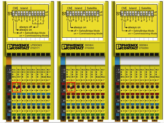
NOTE: For each SAFETY module, its configuration (island and satellite) must be indicated through switches on the module itself, as well as defined by the SAFECONF project.
Robox ID
Each island is identified through a Robox ID (r.id), and can be connected to motion control via AXIOLINE, or over an EtherCAT line using an AXL_BK_EC.
The island connected via AXIOLINE will necessarily have r.id = 0; all other islands will have a r.id = 1-:-n, set during project configuration.
NOTE: To get more diagnostics regarding the status and any alarms present of the SAFETY islands, use the mreport command.
Island configuration via Axioline
From the RDE project, open general window --> Configuration --> Hardware, enter the device used (e.g. RP2), then select the "Axioline Modules" folder, press the INS key, and enter the modules connected via AXIOLINE in order from closest to the control to furthest away (these modules will all have r.id=0).
Once all modules have been entered, double-click on them with the mouse, and for each one indicate the parameters that can be set:
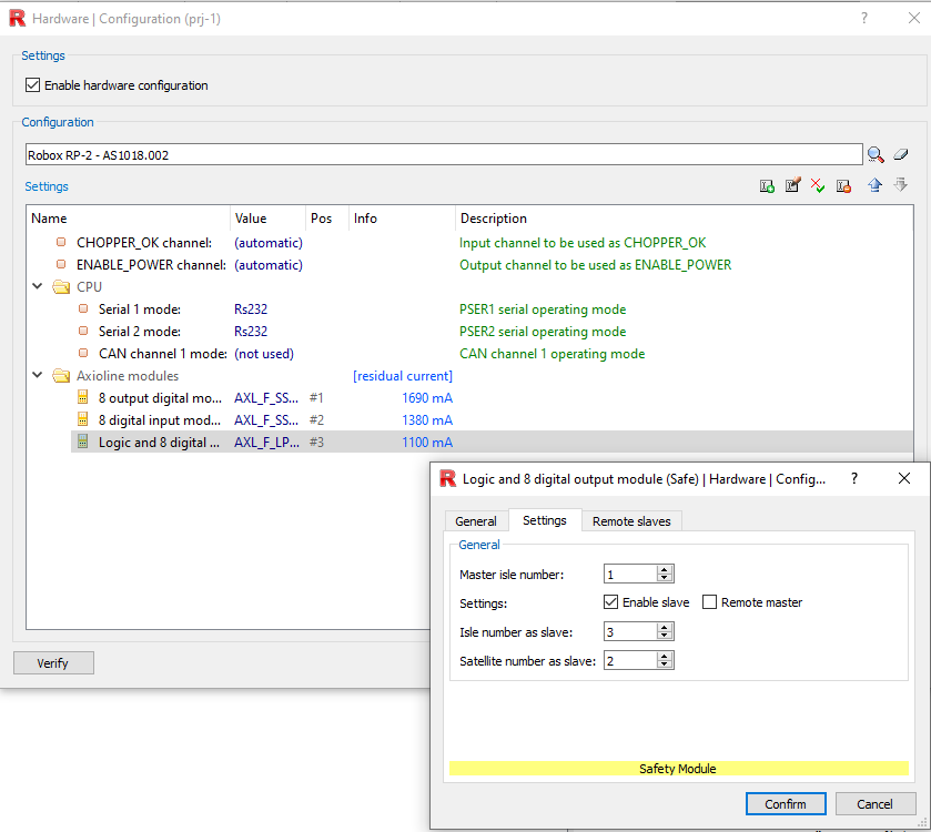
Example with 3 SAFETY modules present on AXIOLINE, where LPSDO8 is also imposed as the slave of island 3. Note that the number assigned to the modules in the "Pos" column is the one used by the ADD_SAFETY command (slot).
•For the SSDI8 and SSDO8 modules, a description of them (optional), the I/O address (automatic default), the island to which they belong, and their satellite
•For the LPSDO8, a description of the module (optional), the I/O address (automatic default), the island to which it will be master (and thus belong to as satellite 0), and the island, if any, to which it belongs as slave, with its associated satellite.
From RTE34.24.11 you can also set any remote modules (see chapter below).
Cross communication between remote LPSDOs
From RTE 34.24.11, cross communication between two LPSDO8 modules present on different controllers is possible as long as they are both connected in Axioline.
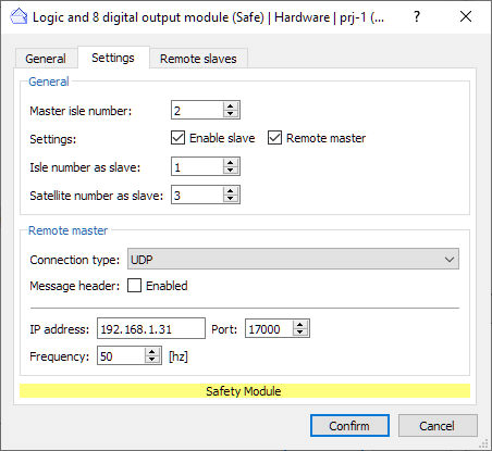
For the slave LPSDO8, double-click on the module, "Settings," set the "Remote Master" flag and set the island to which it belongs as slave and the resulting satellite, the master connection (TCP or UDP), the message header exchange (if any), the IP address and port of the master, and the message exchange frequency.
For the LPSDO8 master, double-click on the module, "Remote Slaves," add a new module and set the slave satellite, connection (TCP or UDP), header message exchange (if any), slave IP address and port, and message exchange frequency.
Island configuration via EtherCAT
In order to connect via EtherCAT line, SAFETY modules need the AXL_BK_EC module (For more information on setting up an EtherCAT line, press here).
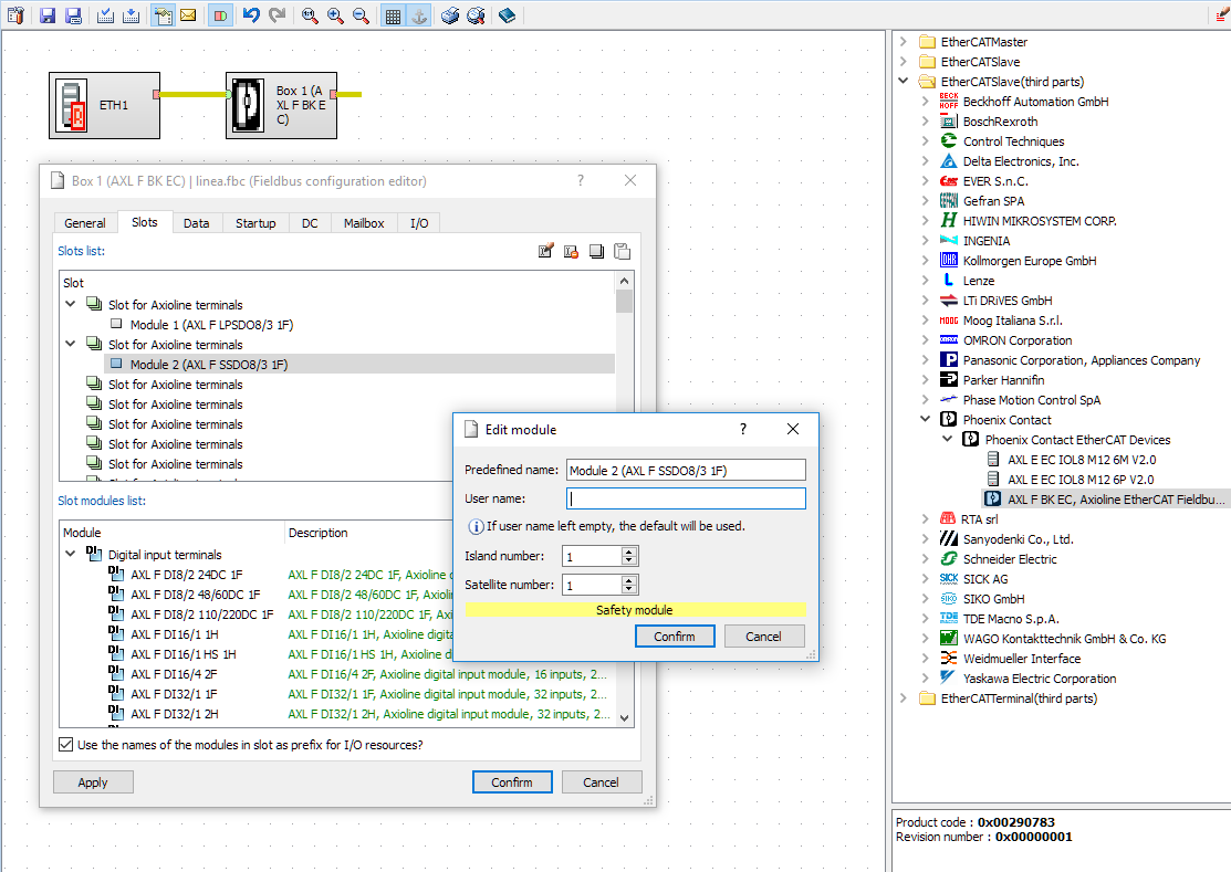
Once the line is configured, double-click on the "Box 1" icon --> "slots" and enter all connected modules present, in order from closest to the AXL_BK_EC to furthest away.
Click above each module to enter the necessary information, finally give "Confirm".
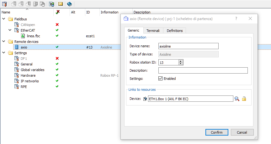
Generated the EtherCAT configuration, go back to the project configuration and press right mouse button, "New" --> "Remote Device..." --> "Axioline", then set all parameters in Generic, Terminals and Definitions.
Island configuration via Ethernet (Modbus/TCP)
In order to operate connected via Ethernet line communicating via Modbus/TCP, SAFETY modules need the AXL_BK_ETH module.
For configuration, it is sufficient to have the PCMBC.CFG file in the flash.
Project safety files.
Each island in the project will have its own BINFILE.BIN file that must be placed inside a folder in the Compact Flash:
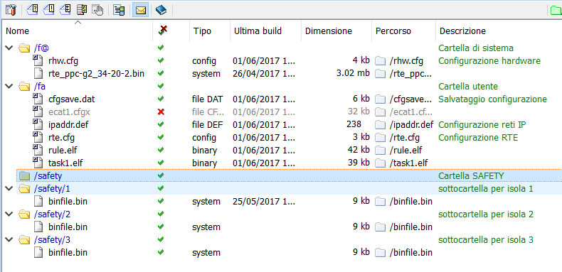
•From RDE project, open project window --> "flash files", press right mouse button and select "Add folder...", then select "Custom" and give as folder path " /safety " and possibly add a description of the folder
•For each island in the configuration, create a subfolder of "safety" that has the island number as its name. To do this, follow the previous step again and when choosing the folder path, write (e.g., for island 1) " /safety/1 "
•For each subfolder, right-click on it, select "Add file..." and choose the corresponding BINFILE.BIN file (folder 1 will have the .BIN file concerning island 1)
Online Debugging via Safeconf
Since RTE 34.24.3, modbus implementation has been added to use online debugging with Safeconf.
Robox side configuration:
•For each island there must be a modbus configuration file 'MODBUS_SAFE_n.CFG' composed as follows:
MODBUS_TCP_PORT [-P port] [-C maxconn]
[ERROR_ON_REPORT]
[RUN-TIME_INFO]
•The defaults are as for standard modbus, the software takes care of checking if the port is not already used by modbus and if so gives warning
Safeconf side configuration:
1.Open the project
2.Right-click on the LPSDO and choose 'Online configuration...'
3.From the window that just appeared, select 'Generic Modbus/TCP device' and press 'Next'
4.Enter the correct IP address and press the 'View Expert Settings' button
5.Set the correct port as per the configuration
6.Make sure that the Field Register Control Code is '0'
7.Make sure that the Register Values field is '352'
8.Press 'Test Connection...' to verify that the IP and port are valid
9.Press 'Finish'
10. Wait a moment and the words 'PLC: connection established' should appear on the status bar on the right.
11. At this point it should be possible on the menu bar to select the 'Secure PLC' menu and the item 'View online values'
Available functions
SAFE_APPL_ACK |
Sets the value of the Application Acknowledge of a safety island |
SAFE_APPL_DIAG |
Returns the status of the Application Diagnostics of a safety island. |
SAFE_DIAG |
Returns the diagnostic register of the desired satellite |
SAFE_DIAG_RESET |
Sends a Diagnostic Reset to the selected satellite |
SAFE_ENAB_OUT |
Imposes the value of the selected island's output enable register |
SAFE_OPER_ACK |
Imposes an Operation Acknowledge on the selected satellite |
SAFE_STS |
Returns the input/output safety status of the selected satellite |
SAFETY Directives
Manages the mapping of a safety line |
|
Shows the timings of all modules in a safety island |
SAFETY Alarms