Introduction
EtherCAT (Ethernet for Control Automation Technology) is a deterministic industrial Ethernet technology originally developed by Beckhoff Automation. The EtherCAT protocol, published in the IEC61158 standard, meets hard and soft real-time requirements in automation, test and measurement systems, and many other applications.
In an EtherCAT network, information is exchanged via Ethernet frames, each in turn consisting of one or more datagrams. Regardless of the physical topology (line, cascade, star, ...), all frames are sent from the master through all slaves and return to the master after completing the loop. The data carried by the frames are processed by the slaves 'on-the-fly'. The delay incurred by the frame is equal only to the physical traversal time of the slave. (See official EtherCAT website for more information.)
This technology is managed by Robox through its own controllers, whose Ethernet channels can handle an EtherCAT line with CoE (CANopen over Ethernet) and SoE (Servodrive over Ethernet) protocol in Sync mode or Distributed Clock (DC) as master.
Up to 1024 terminals can be managed.
Bookmarks
Related arguments
Configuration
In order to communicate via EtherCAT, the Robox control needs two files, configurable from the RDE project, which must be present in the compact flash (or SD) and which contain all the specifications regarding the line:
•The ECATn.CFGX file: This file contains the configuration of an EtherCAT network channel. "n" represents the channel number, so ECAT1.CFGX contains the configuration of the first Ethernet channel. This is an XML file that is assumed by RTE only when the control is turned on and is used both to parameterize the network and to learn about the data packets exchanged with each device present
•The FB.CFG file: This file contains the association between the data exchanged in the EtherCAT network, described in the ETHn.CFGX file, and the Robox variables. It is an Ascii file that is assumed by RTE only when the control is turned on. This file is generated by RDE based on the defined global variables, remote devices, and configured axes
NOTE: Since RTE 34.28.2, the optional auxiliary file FB2.CFG has also been added.
Generation of such files is handled by RDE project:
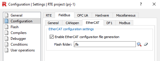
Open RTE Project--> Properties--> Configuration--> Fieldbus, make sure generation of fb.cfg file (under General) and EtherCAT configuration (under EtherCAT) is enabled.
EtherCat Network (File ECATn.CFGX)
From the workspace press File--> New File... (or give quick command Ctrl+N), enter the name and give it as an extension .fbc (Fieldbus Configuration Files). Then create it under the project folder.
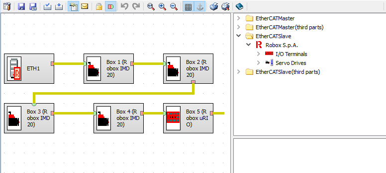
Once the file is created, the appropriate RFBCED configurator window (Robox fieldbus configurator Editor) will automatically open, from which you can add devices connected to the EtherCAT line.
NOTE: Configuring control as an EtherCAT slave node is available from RTE 34.30.0 only for RP-2 control AS1018.012.
NOTE: From RTE 34.5.1, it is possible to configure all devices and then report those that are not connected using the keyword ECAT_SLAVE_OFF.
After entering all devices, save and then close the window.
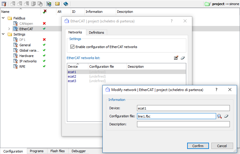
Open the RTE project--> Configuration--> double-click on "EtherCAT"--> check "Enable configuration of EtherCAT networks"--> double-click on ecat1--> select the newly created .fbc file under "Configuration files".
NOTE: With RDE < 3.50 you must link the CFGX output file obtained from the external configurator.
Once given confirmation, from project configurator press the right mouse button and select Generate -> EtherCAT configuration only (or generate all). At this point, the file ECATn.CFGX has been created under the project folder and at the next Make or Rebuild it will be loaded into the folder corresponding to the alias ECAT_DIR.
Data exchanged in EtherCat (File FB.CFG)
As mentioned earlier, the contents of this file depend on the use of global variables, the remote devices connected via EtherCAT, and the axes, also connected via EtherCAT, in the project.
The FB.CFG file must be located in the FB_DIR folder alias.
FB2.CFG
Since RTE 34.28.2, the optional FB2.CFG file, auxiliary to FB.CFG, has been added. This file is not related to ECAT2.CFGX and can contain any mapping (such as FB.CFG).
FB2.CFG is only loaded if FB.CFG is also present (it can also be an empty file) and the latter does not have an error in it.
The FB2.CFG file must be in the FB_DIR folder alias.
Remote Device Management
From RTE project--> Configuration press the right mouse button and select New--> Remote Device. Then select the type of remote device to be used.
To connect the remote device to the EtherCAT line, select the related link under Links to Resources section.
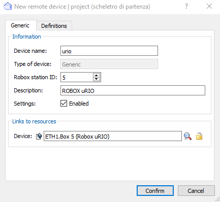
Then set all other parameters related to the remote device.
Axis management
From RTE project--> Configuration press the right mouse button and select New--> Axis.
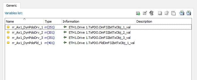
To link the axis to the EtherCAT line, select Fieldbus--> Device--> check "Associate the axis to a remote device"--> select the Robox ID--> link the axis related device, status word and control word. Under Fieldbus--> Links link the additional information contained in the PDOs to the axis variables.
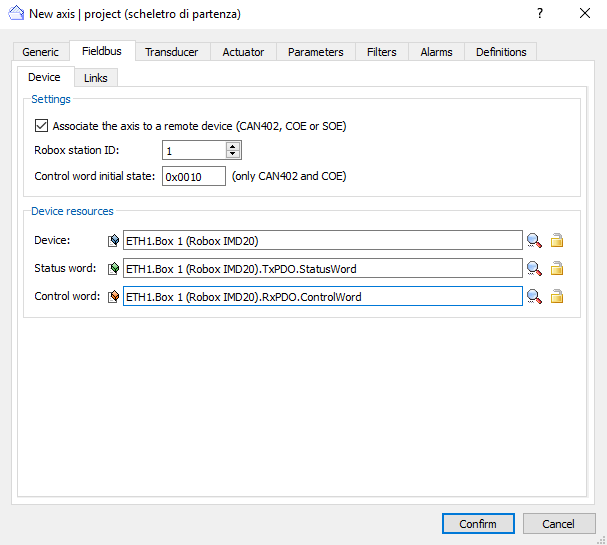
Then set all other axis-related parameters (general, transducer, actuator...).
WARNING: Until RTE 3.52, there was no "Field Bus" window, and all the information in it was instead entered by creating a remote device (Drive CAN402), which was then associated with the axis. This method can still be used today.
Global variables
From RTE Project -> Configuration, select "Global Variables" to associate the variables contained in the PDOs with the axis control variables (global variables).
Once the global variables, axes, and remote devices have been configured, generate the configuration from RTE project in order to update the FB.CFG file and then load it into flash through a make or rebuild operation.
NOTE: From RTE 34.27.5, the number of definable variables connected to ethercat has increased from 3000 to 6000 for arm-a9 cpu only.
Status Variables
The following status variables are available for each EtherCAT network created:
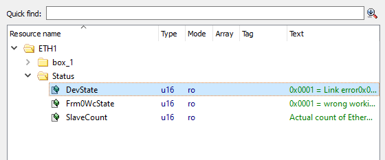
•DevState: bit mask describing the state of the device
•0x0001 = Link error at primary port
•0x0002 = I/O blocked as a result of link error (I/O reset requested)
•0x0004 = Link error at redundant port (redundancy mode)
•0x0008 = Missing frame (redundancy mode)
•0x0010 = Out of send resources (I/O reset required)
•0x0020 = Watchdog triggered
•0x0040 = Ethernet driver (miniport) not found
•0x0080 = I/O reset active
•0x0100 = At least one device in the INIT state
•0x0200 = At least one device in the PRE-OP state
•0x0400 = At least one device in the SAFE-OP state
•0x0800 = At least one device indicates an error state
•0x1000 = Distributed Clock not in sync
•Frm0WcState
•0x0001 = wrong working counter by 1
•0x0002 = wrong working counter by 2
•0x0004 = wrong working counter of 3
•...
•0x4000 = wrong working counter by 15
•0x8000 = completely missing frame
•SlaveCount: actual number of EtherCAT slaves detected on the network
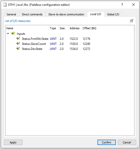
To be able to map them to a Robox resource follow this procedure: from RTE project--> Variables--> Global variables--> Right click and select New variable (Ins) (figure 1)--> enter at least the "Type" field--> click on the magnifying glass on the "Source" field line--> ETHn--> Status (figure 2).
Figure 1:
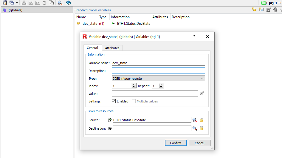
Figure 2:
Functions/Instructions
co_statusword() |
Function that returns the contents of the statusword of the indicated ws |
co_controlword_state() |
Function that writes the bits of the control_word (object 6040H) |
co_controlword_om() |
Function to impose status on the drives (operation mode specific, halt , manufacturer specific) |
co_rerr() |
Function to read the last emergency message generated by the indicated ws |
co_par_download() |
Instruction to upload to a device connected via can the parameters contained in a file in the flash of the Robox control |
co_par_upload() |
Instruction to update in the flash of the Robox control a parameter file by reading values from the device connected via can |
co_rnmt() |
Function that returns the NMT state of the indicated ws |
co_wnmt() |
Function that imposes NMT state on the indicated ws |
co_robj() |
Function to read objects from fieldbus |
co_wobj() |
Function to write objects from fieldbus |
coe_robj() |
Function to read objects from fieldbus |
coe_woj() |
Function to write objects from fieldbus |
co_send_sdo() |
Writing SDO |
co_asw_sdo() |
Read SDO |
ecat_dev_on_off() |
Enables/disables a device on EtherCAT line |
ecat_get_state() |
Reads the status of the EtherCAT line |
ecat_probe() |
Reads the information of a device on EtherCAT line |
ecat_set_state() |
Imposes the state of the EtherCAT line |
Keywords
Status of the status word (object 6041H) |
|
Status of the control word (object 6040H) |
|
Displays information about the transducer |
|
Allows you to specify how to extrapolate the sub-device number from the emergency message |
|
Number of references defined |
|
Number of transducers defined |
|
Masks EtherCAT networks with fewer nodes than desired |
|
Operational status of nodes |
|
Number of nodes actually present |
|
Number of nodes configured |
|
Number of nodes expected to be disconnected |
|
Number of nodes expected to be present |
|
Operational state of the master |
|
Number of synchronous frames lost |
|
Mask EtherCAT networks to force state reading |
|
Diagnostic fieldbus alarm mask |
|
Mask of configured fieldbus master channels |
|
Mask of axes that have the defined fieldbus type reference |
|
Parameter to configure the maximum number of EtherCAT frames that can be lost consecutively before the system generates an 8x ECAT xx No Communic alarm. |
|
Parameter to know the number of consecutive EtherCAT frames that currently result as lost |
|
SYS_CFG_2.21 |
Sets all EtherCAT slaves to SAFE-OP mode when the operating mode is changed to loading |
For other EtherCAT Slave keywords see EtherCAT Slave Configuration.
SHELL commands
Displays the emergency messages information |
|
Displays the emergency messages of the specified station |
|
Displays the NMT status of the specified station |
|
Displays the value of the specified object |
|
Displays the CAN402 machine status of the specified station |
|
Displays the NMT status of the specified station |
|
Writing the specified object |
|
Displays the diagnostic of the specified station |
Device commands
Allows SDO (service data object) messages to be sent to workstations on the network |
|
Allows reading objects on CoE fieldbus |
|
Allows writing objects on CoE fieldbus |
|
Permits to enable/disable immoderate timeout on waiting for response on CoE object management via mailbox (e.g., drive response on object change for transducer type selection) |
|
Displays the current error message present on the specified workstation |
|
Displays the current NMT status of the specified workstation |
|
Displays status code of the specified workstation |
|
Disables issue of Emergency messages |
|
Command to impose NMT command on the specified station |
|
Performs reading of internal registers of an ethercat device using incremental address |
|
Performs writing of the internal registers of an ethercat device using incremental address |
|
Performs reading of the internal registers of an ethercat device using absolute address |
|
Performs writing of the internal registers of an ethercat device using absolute address |
|
Displays the NMT status of the EtherCAT line |
|
Performs device discovery on an ethercat line |
|
Sets the NMT state of the EtherCAT line |
|
Sets the number of nodes that can be disconnected from an EtherCAT line without generating alarms |
|
Sets a filter time for alarms after the ECAT_SLAVE_DISCON=0 command. |
|
Sets presence/absence of nodes in the EtherCAT line |
|
Enables/disables nodes present on the EtherCAT line |
|
Sets the status of a node in the EtherCAT line |
|
Displays the value of the specified FIELDBUS variable |
|
Displays the type of transducer configured for the axes |
|
Displays the type of position reference configured for the axes |
|
Displays the speed reference type configured for the axes |
|
Displays the type of torque reference configured for the axes |