Introduction
Configuration of the control as an EtherCAT slave node is available from RTE 34.30.0 only for RP-2 control AS1018.012.
The control, as an EtherCAT node, allows up to 400 Bytes to be exchanged for both directions.
The configuration of data exchanged from the control to the master, viewed as an EtherCAT node, is determined by the FBSLAVE.CFGX file, located in the microSD, in the FB_DIR folder (default /fa).
The configuration of exchanged data is organized into 10 blocks of 40 bytes for each of the 2 directions, with data of the same type; the number of different data will depend on their type.
Bookmarks
Related arguments
Configuration
Configuration is done by connecting to ETH FB-S 4 (input) and ETH FB-S 5 (output) ports.
The type of fieldbus used can be set:
•from RDE hardware configurator
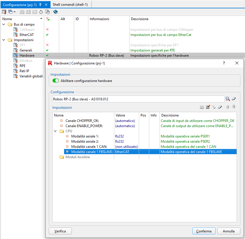
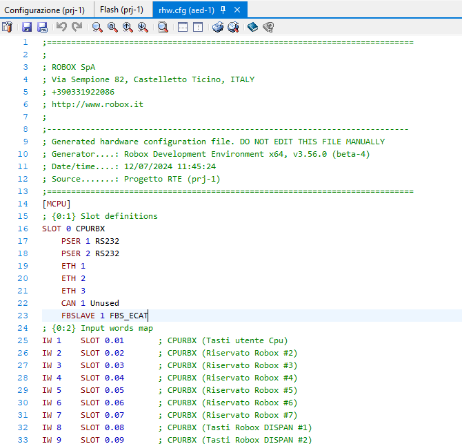
•from RHW.CFG file manually
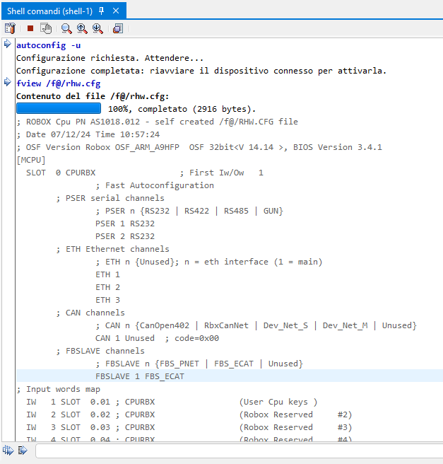
•via shell autoconfig command, specifying the Update (-U) option
If this is the first time the controller is configured as an EtherCAT slave, the firmware file 'Fbs_ecat.eef' must be present in the /f@/ folder of the microSD. The file is loaded automatically, at startup, if the interface is not already programmed or is programmed with a different version.
The /fa/ or FB_DIR folder must contain the file FBSLAVE.CFGX, with the configuration of the data exchanged with the master.
FBSLAVE.CFGX configuration file
The fbslave.cfgx control configuration file is divided into 3 parts:
•definition of the file type (xml) and general characteristics regarding the configuration
•definition of data received from control (fieldbus, channel, endian)
•definition of data sent from control (slot, data type, number of objects)
Master Configuration
An ESI file describing the exchanged data available is provided for node configuration on the master. The node does not provide for free configuration of the exchanged data, but makes available in the various slots a fixed configuration based on the type of data exchanged, which must be correlated with what is selected in the configuration file on the control for the various slots. A type-dependent number of variables are exchanged for each slot, considering a maximum of 40 bytes per slot.
The modules available in the ESI file are as follows:
Module name |
Data type |
Number of data |
Block type in FBSLAVE.CFGX "objType" |
|---|---|---|---|
U16_From_RBX |
16-bit unsigned integer |
10 |
U16 |
I16_From_RBX |
16-bit signed integer |
10 |
I16 |
U32_From_RBX |
32-bit unsigned integer |
10 |
U32 |
I32_From_RBX |
32-bit signed integer |
10 |
I32 |
U64_From_RBX |
64-bit unsigned integer |
5 |
U64 |
I64_From_RBX |
64-bit signed integer |
5 |
I64 |
F32_From_RBX |
Real 32 bit |
10 |
Float |
F64_From_RBX |
Real 64 bit |
5 |
Double |
NOTE: The slot identified as Module 21 present in the last slot should always be left configured, even if it is not currently used for data exchange.
EtherCAT network configuration
In RDE, after opening the EtherCAT configurator, once the desired network file is selected, select from EtherCAT slaves--> Robox S.p.A.--> Robox generic motion controller--> RTE ECAT Slave.
Once entered, in the device settings under the Slots section, select the modules equivalent to those programmed within the control in the FBSLAVE.CFGX file.
Once the configuration of the modules is done, in the Data section uncheck any checkboxes related to PDO assignment and configuration.
If the number of slots does not match the programmed slots, so the size of the exchanged data does not match, when connecting the node to the network, the master will generate an error in changing state from PRE-OPERATIONAL to SAFE-OPERATIONAL.
NOTE: If the data is incorrect, but the slot number matches, no error will be reported.
If there is an error in the number of slots, giving the ECAT_PROBE shell command on the Master control will result in an AL Status = 0x12 (PRE_OPERATIONAL + ERROR status); in addition, if the error is in the number of slots to the node (Slot_To_x), the return code will be 0x001d, while in the case of slots from the node (Slot_From_x) the code will be 0x001e.
Alarm 9246 'FBS_ECAT(1) Interface error (5)' will come out on the Slave control, and the LEDs will indicate the status condition PRE-OPERATIONAL + ERROR.
Keywords
BAD_CONFIG.13 |
Error in EtherCAT Slave Configuration |
FB_SLAVE_CFG.15 |
EtherCAT Slave configured |
Show FB_SLAVE configuration information in rhw.cfg |
|
Show information about the current FB_SLAVE configuration |
|
Shows information about the firmware version of the FB_SLAVE board |
|
Shows information about the configuration status of the FB_SLAVE board |
|
FBS_INFO_1[1] |
Type of firmware installed on the board |
FBS_INFO_1[2] |
Channel number |
FBS_INFO_1[3] |
Fieldbus interface status |
FBS_INFO_1[4] |
Status of the interface firmware |
FBS_INFO_1[5] |
EtherCAT node status |
FBS_INFO_1[6] |
Number of messages received by EtherCAT |
FBS_INFO_1[7] |
Number of messages transmitted to EtherCAT |
FBS_INFO_1[8] |
Number of Sync received (SM) |
FBS_INFO_1[9] |
Number of Sync received (DC) |
FBS_INFO_1[10] |
Type of synchronization |
FBS_INFO_1[11] |
Cyclic message time (nanoseconds) |
System time to Sync interrupt (seconds) |
|
TFB on arrival of Sync interrupt |
|
TFB at the arrival of the Sync 0 interrupt |
|
Status of the ESM (EtherCAT State Machine) of the channel |
|
Fieldbus time to Sync 0 interrupt (seconds) |
|
Fieldbus data update time |
For other EtherCAT keywords see EtherCAT Communication (COE).
Alarms
FBS_ECATS(ch) configuration fault (code) |
|
FBS_ECATS(ch) lost communication (code) |
|
FBS_ECATS(ch) interface error (code) |