Diagnostics performed at switch on
Operation 1
In RBXM/RBXE/RMC (Modular) controls, at switch on RTE checks for the presence of the CANOpen DS301/401/402 protocol manager on the flashcard.
In uRmc/RPx controls, the CANOPEN management software is integrated into RTE, so this operation is not performed.
The file differs depending on the CAN.INT board used:
•CODMvvrr.UFW for CAN.INT nCh (where n is the number of CAN channels on the board)
•CODMvvrr.086 for CAN.INT and CAN/PROF in CAN mode
If this file is missing alarm 9204 C402 (0) Configuration fault (-3) is generated and the status of the LEDs on the canbus board is: LR on steady, LG on steady.
On Parker boards and on uRMC this operation is omitted since the CANOpen manager is integrated in the RTE firmware.
NOTE: With a reset command, this alarm is deleted from the alarm stack. Use the FLOAD directive to load the file into the flashcard.
Operation 2
The presence on flashcard of the COCn.CFG file is checked, which contains all the information about the devices on the network.
If this file is not found, alarm 9204 C402 (n) Configuration fault (1) is generated and the status of the LEDs on the canbus board is: LR flashes twice fast, waits one second and repeats, while LG is off.
NOTE: With a reset command, the alarm is deleted from the alarm stack. Use the FLOAD directive to load the file into the flashcard.
Operation 3
RTE executes the commands in the COCn.CFG file.
If the connection cannot be established, alarm 9204 C402 (n) Configuration fault (25) is generated and the status of the LEDs on the canbus board is: LR on steady, LG off.
CAN402 Diagnostics
The following will illustrate an example with the purpose of showing the tools and shell directives provided by Robox software to investigate more thoroughly any errors on the CANBus line. The example simulates the absence of a CAN station. At system startup we type the D AL (display alarm) directive to see if there are any alarms.
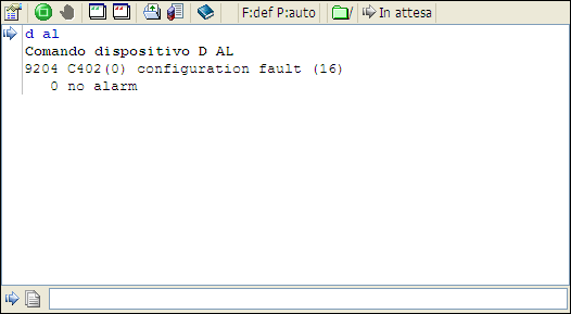
The RTE firmware reports the presence of an error related to CAN channel 0. You can find the description of alarm 9204 C402(0) configuration fault (16) in this manual. Insights into the system status can be found through the report -o instruction (the -o option is to get the report from the last "old" message).
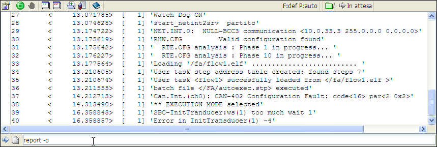
As can be seen on line 37 there is a more extended form description of the error, but it does not say anything more than the previous directive. You can get more description through the report -o -s command, which displays the operating system part of the report.
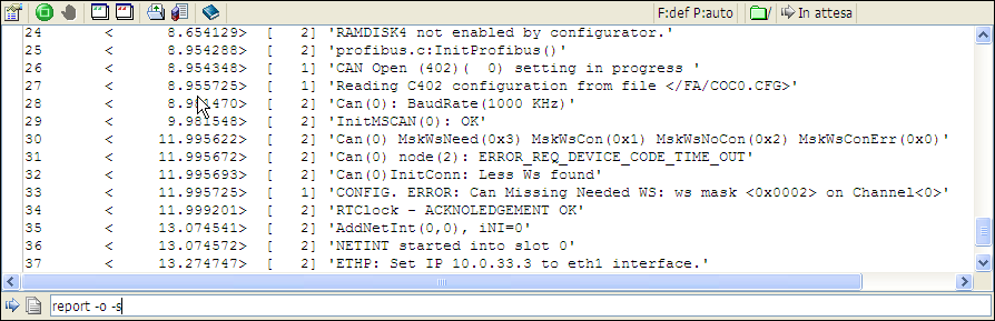
As can be seen from line 26 to 33 there is the relative description of the CAN channel status. On line 30 there are the values of some bit masks whose meaning follows:
•MskWsNeed: bit mask indicating the workstations required for proper functioning of the CAN network. In the case shown, the value is 0x3 so the 1 and 2
•MskWsCon: bit mask indicating the workstations correctly connected to the CAN network. In the case in figure the value is 0x1 so the 1
•MskWsNoCon: bit mask indicating the workstations that should have been connected but are not present. In the case in figure the value is 0x2 so the 2
•MsWsConErr: bit mask indicating workstations connected but in error. In the case in the figure, the value is 0, so there are none
Line 31 informs that CAN node 2 did not respond within the time limits provided by the Robox control. Line 32 says that the system found fewer CAN workstations than it expected. Line 33 reports an error informing the user that CAN channel 0 workstation 2 was not found. It is possible to tell RTE not to throw alarms in this situation, this allows us to debug the rest of the system. The coc configurator allows us to easily achieve this by removing the flag: "Node must always be present" from the "General" subsection of the "General Settings" folder. The configurator contains other items, described in the online manual dedicated to it, that allow us to debug the CAN network step by step, thus being able to isolate the problem.
The user has the ability via application to analyze the status of CAN402 communication at any time by requesting that all diagnostics of a certain type be downloaded to a block of registers chosen by him.
This request should be made using the following predefined variables:
Name |
Description |
|---|---|
CAN_DIAG_CH |
Indicates the can channel whose information is being requested |
CAN_DIAG_IDX |
Index of the first of the 8 R registers into which diagnostics will be downloaded |
CAN_DIAG_N |
Identifier of the type of diagnostic requested. The following codes are allowed: |
List of diagnostic codes:
Code |
Description |
|---|---|
Reset Diagno area |
|
Alarm counters on the CAN network |
|
Diagnostics on asynchronous message handling SDO + AsyncRPDO |
|
Workstation alarms and masks requested, present, absent, and on NMT commands |
|
Diagnostics on WsCon remote connection result (stations 1-16) |
|
Diagnostics on message transmission times since RBXMSyncInt arrival (16-bit times, so maximum RBXMSyncInt sampling time < 65535us) |
|
Diagnostics on message transmission times since arrival of RBXMSyncInt (32 bits times) |
|
Counters of total SyncTxPDO messages transmitted |
|
Counters of SyncTxPDO messages transmitted with sync enabled for all workstations |
|
Counters of SyncTxPDO messages transmitted with sync enabled for all workstations |
|
Counters of SyncRxPDO messages received with sync enabled of all workstations |
|
Counters of Remote Frame messages per request AsyncTxPDO transmitted and received of all workstations |
|
Counters (16 bits) of SyncRxPDO1 messages received for the 16 workstations |
|
Counters (16 bits) of SyncRxPDO2 messages received for the 16 workstations |
|
Counters (16 bits) of SyncRxPDO3 messages received for the 16 workstations |
|
Counters (16 bits) of SyncRxPDO4 messages received for the 16 workstations |
|
Counters (16 bits) of SyncTxPDO1 messages transmitted with sync enabled for the 16 workstations |
|
Counters (16 bits) of SyncTxPDO2 messages transmitted with sync enabled for the 16 workstations |
|
Counters (16 bits) of SyncTxPDO3 messages transmitted with sync enabled for the 16 workstations |
|
Counters (16 bits) of SyncTxPDO4 messages transmitted with sync enabled for the 16 workstations |
|
Counters (16 bits) of messages related to logical workstation 1 |
|
Counters (16 bits) of messages related to logical workstation 2 |
|
Counters (16 bits) of messages related to logical workstation 3 |
|
Counters (16 bits) of messages related to logical workstation 4 |
|
Counters (16 bits) of messages related to the logical workstation 5 |
|
Counters (16 bits) of messages related to the logical workstation 6 |
|
Counters (16 bits) of messages related to the logical workstation 7 |
|
Counters (16 bits) of messages related to the logical workstation 8 |
|
Counters (16 bits) of messages related to the logical workstation 9 |
|
Counters (16 bits) of messages related to the logical workstation 10 |
|
Counters (16 bits) of messages related to the logical workstation 11 |
|
Counters (16 bits) of the messages related to the logical workstation 12 |
|
Counters (16 bits) of the messages related to the logical workstation 13 |
|
Counters (16 bits) of messages related to the logical workstation 14 |
|
Counters (16 bits) of messages related to the logical workstation 15 |
|
Counters (16 bits) of messages related to the logical workstation 16 |
|
Diagnostics on times related to PLL handling on sync msg transmission (times in counts at 40MHz, i.e. 1/40th of us) -not available on AS1016 (Parker)-board |
|
Diagnostics on network times with PLL (sync times in counts at 40MHz, i.e. 1/40 us, others in us) -not available on AS1016 (Parker)- board |
|
0x0100 |
Resets error counters and alarms. Leaves previous information selection in the Diagno zone unchanged |