Creating a new axis
Up to 32 axes can be included in an RTE project. An axis can eventually be associated with a node in an EtherCAT or CANopen network. You can create axes that are not associated with any ECAT/CAN device. You can also create axes that are configured only as a transducer or only as an actuator.
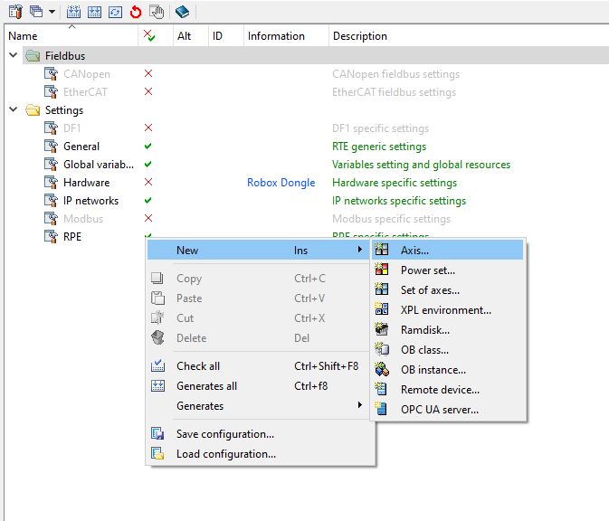
To add a new axis to your RTE project, from the project configurator page: right click -> New -> Axis..
Axis configuration
Settings: General
On the "General" page of axis settings you have to enter a name for the axis and its ID. If necessary, you can enter an alternative name and description. The axis name, or possibly its alternative name, may be used when writing the program with the R3 language instead of its ID. For example (in according with the below image), to refer to the ideal position of axis 1, instead of writing IP(1) it will be possible to write IP(axis_1) or IP(ax1).
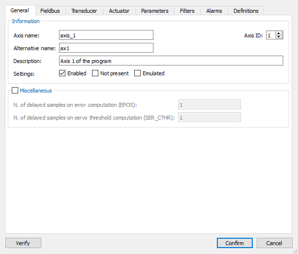
The number of system synchronous cycles (called rule sampling or just sampling) for position error calculation and error threshold can be configured. They are usually configured in case the axis is associated with an EtherCAT or CANopen device.
Settings: Field Bus
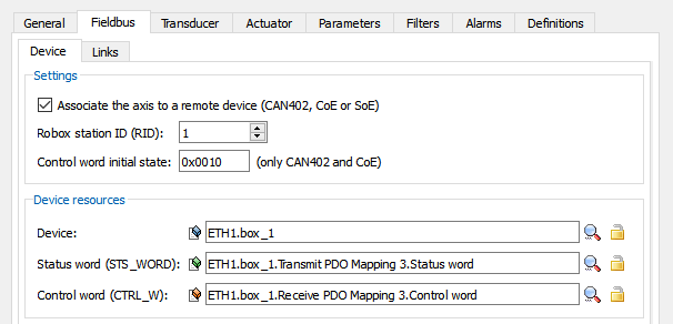
In case the axis is associated with an EtherCAT or CANopen device, check the option "Associate the axis to a remote device (CAN402, COE or SOE)". You can choose the value that the control word will take when the control starts communicating with the device.
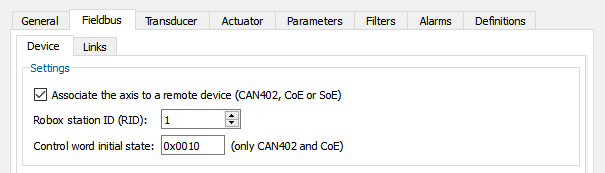
In case of CANopen devices you will have to indicate the Robox station Id associated with the axis, it is used to associate the axis with a node in the CANopen network; in fact, during CANopen network configuration the possibility is given to indicate for each node the ID of the associated Robox device. The association of CANopen network resources with Robox resources is done through the CANopen editor.
In the case of EtherCAT devices you will need to associate network resources with Robox resources. In case you have already configured the EtherCAT network, a command is available that automatically updates the axis configuration, associating the standard DS402 profile objects (statusword, controlword, target velocity) with Robox resources: right-click on the .fbc file -> Update Configuration...
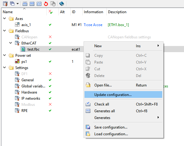
The "Update Configuration..." command can also be used to create a new axis if the appropriate option is checked.
NOTE: The axis name given on the "General" page must match the EtherCAT device Label, otherwise RDE will fail to associate the axis in the RTE configuration with the EtherCAT device.
If the procedure was successful, you will find the correct settings for your axis on the "Field Bus" (see also "Device" and "Connections" subpages), "Transducer" and "Actuator" pages.
The following resources must be connected to work properly:
•"Device" sub-page: Device, Status word and Control word.
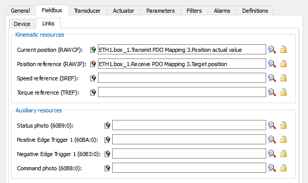
•Sub-page "Connections": Current position and, depending on the type of reference sent to the actuator, one of the following: Position reference, Speed reference, Torque reference
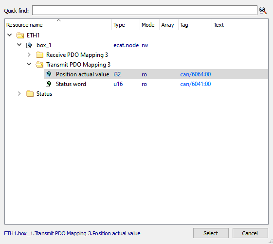
To manually link an EtherCAT resource with a Robox resource, click on the magnifying glass on the row corresponding to the Robox resource you want to configure, a window will open from which you can search and select the resource you want to associate
Settings: Transducer
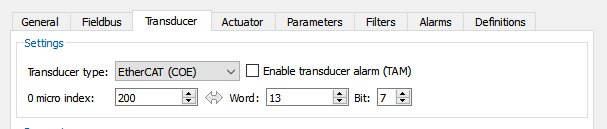
The type of axis transducer is selected via the drop-down menu. Optionally, you can choose to enable transducer alarm(tam) and indicate the index of the zero micro associated with the axis. The available parameters depend on the type of transducer selected.
Different parameters will be available. The table below summarizes which parameters are available depending on the transducer type.
Parameters |
Incremental encoder |
Absolute (SSI) |
Analog input |
CANopen |
Integer register |
Real register |
EtherCAT (COE) |
EtherCAT (SOE) |
Local Axioline (stepper motors only) |
|---|---|---|---|---|---|---|---|---|---|
Transducer index |
x |
x |
|
|
|
|
|
|
|
Offset |
|
x |
x |
|
|
|
|
|
|
Analog input index |
|
|
x |
|
|
|
|
|
|
Minimum value |
|
|
x |
|
|
|
|
|
|
Maximum value |
|
|
x |
|
|
|
|
|
|
Register type |
|
|
|
|
x |
x |
|
|
|
Register index |
|
|
|
|
x |
x |
|
|
|
Communication freq. |
|
x |
|
|
|
|
|
|
|
Drive type |
|
|
|
x |
|
|
x |
x |
|
Auxiliary parameter 1 |
|
|
|
x |
|
|
x |
x |
|
Transducer usage |
|
x |
|
x |
x |
x |
x |
x |
x |
Retentive axis position |
x |
|
|
x |
x |
x |
x |
x |
x |
Micro of internal 0 |
|
|
|
|
|
|
x |
|
|
Data size |
|
x |
x |
x |
x |
|
x |
x |
x |
Absolute data size |
|
|
|
x |
|
|
x |
x |
|
Transducer alarm register |
|
|
|
x |
x |
x |
x |
x |
|
Slots in Axioline bus |
|
|
|
|
|
|
|
|
x |
Board channel index |
|
|
|
|
|
|
|
|
x |
Below you will find the description of each parameter:
•Transducer index: index of the transducer to be used as the transducer for the axis. The transducer index is associated with the devices connected to the control in the hardware configuration
•Offset: offset to be subtracted from the value read by the transducer
•Analog input index: index of the analog input to be used as transducer
•Minimum value: minimum detectable value below which the transducer alarm is generated
•Maximum value: maximum detectable value below which the transducer alarm is generated
•Register type: selection of register type, volatile or retentive
•Register index: index of the register you want to use as transducer
•Communication freq: frequency of SSI communication
•Drive type: in case the transducer is associated with an EtherCAT/CANopen device, you have to choose the drive type from the drop-down menu
•Auxiliary parameter 1: auxiliary parameter whose meaning depends on the drive type
•Transducer usage: this option indicates how the position data coming from transducer is to be read:
oIncremental - the position is read from the transducer at each rule sampling and added to the position obtained at the previous rule sampling
oAbsolute - the position read is taken directly from the transducer at each sampling rule beat
oSemi-absolute - the position read is assumed directly by the transducer at each rule sampling, taking into account the number of absolute bits
•Characteristics - Retentive axis position: this option is used to indicate that the transducer is of the retentive type and thus enables the management of the retentive axis position
•Characteristics - Internal micro of 0: this option is used to indicate that the transducer's internal micro of 0 is to be used
•Data size: this option indicates the size of the total data arriving from the transducer in number of bits
•Absolute data size: this option indicates how many bits of the data arriving from transducer are absolute
•Transducer alarm register: this option is for if the user wants to manage the transducer alarm, it indicates the register number that indicates the presence of an alarm. If the register value is non-zero the transducer alarm will be output, otherwise not
•Slot in Axioline bus: used only for stepper motors. Index Axioline bus slot of the device to be used as a transducer for the axis.
•Board channel index: used only for stepper motors. Index of Axioline board channel to be used as transducer for axis
NOTE: See also Transducer configuration for fieldbus.
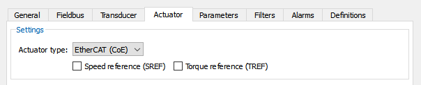
Settings: Actuator
The type of axis actuator is selected via the drop-down menu. It is always possible to indicate if the reference given to the axis is speed(sref) or torque(tref), while the position reference is only available for EtherCAT(COE), EtherCAT (SOE) and CANopen type actuators.
Different parameters will be available. The table below summarizes which parameters are available depending on the actuator type.
Parameters |
Analog output |
CANopen |
Integer Register |
Real register |
Output word |
EtherCAT (COE) |
EtherCAT (SOE) |
Local Axioline (stepper motors only) |
|---|---|---|---|---|---|---|---|---|
Analog output index |
x |
|
|
|
|
|
|
|
Output type |
x |
|
|
|
|
|
|
|
register index for offset |
x |
|
|
|
|
|
|
|
Data size |
x |
x |
x |
|
x |
x |
x |
|
Positive direction sel. channel |
x |
|
|
|
|
|
|
|
Channel sel. negative direction |
x |
|
|
|
|
|
|
|
Drive type |
|
x |
|
|
|
x |
x |
|
Position reference |
|
x |
|
|
|
x |
x |
|
Register type |
|
|
x |
x |
|
|
|
|
Register index |
|
|
x |
x |
|
|
|
|
Index output word |
|
|
|
|
x |
|
|
|
Data diagnostic register |
|
|
|
|
|
|
|
x |
Below you will find the description of each parameter:
•Analog output index: index of the analog output to be used as a reference for the axis
•Output type: indicates if the reference uses any value or only positive or only negative values
•Register index for offset: index of a volatile integer register containing the offset to be added to the reference for the axis
•Data size: size in bits of the reference
•Positive direction sel. channel: index of the digital output channel for the positive direction of travel
•Negative direction sel. channel: index of the digital output channel for the positive direction of travel
•Drive type: the type of drive associated with the actuator
•Characteristics - position reference: enable position reference, the reference passed to the axis will be equal to the ideal position
•Register type: choice of volatile or retentive register to be used as axis reference
•Register index: index of register to be used as reference for axis
•Output word index: index of the output word to be used as reference for the axis
•Data diagnostic register: used only for stepper motors. Index of the first of eight consecutive integer registers to be used as diagnostic
Settings: Parameters
On the "Parameters" page, axis parameters can be set. The values set on this page will be written during control startup. Be warned, as these parameters are by default retentive, if a parameter is not enabled on this page it will not be written during control startup and its value will be equal to the last value set.
Below you will find links to descriptions of the individual parameters.
•kff
Settings: Filters
Position loop filters can be imposed on this page. Refer to the appropriate documentation: Position loop filters.
Settings: Alarms
On this page you can enable the generation of axis-related alarms. The generation of each alarm is enabled by setting the bit of the corresponding bit mask to 1 (bit 0 for axis 1, bit 1 for axis 2, etc.).
Bit mask |
Output condition of the alarm |
Axis parameters involved |
Alarm emitted |
|---|---|---|---|
Position error exceeds servo threshold |
|||
Ideal position exceeds end of strokes limit |
alarm 14 - lower limit reached/allarme 15 - upper limit reached |
||
Ideal velocity exceeds maximum velocity |
|||
Ideal acceleration exceeds maximum acceleration |
Settings: Definitions
On this page you can create constants for use in R3 or R++ programs. Clicking on the icon with the green "+" symbol is given the possibility of entering literally R3, literally R++ and Bit Masks.