When interfacing the drives through a fieldbus the position loop is usually closed directly by the drive. In fact RTE exchanges the data contained in the PDOs at the rules frequency and calculates the new IP (ideal position) for the controlled axes.
If the drives are configured with speed control the user can have the position loop closed by the motion controller as follows :
•Using the default position loop closure, which includes a proportional component (PRO_GAI) and a speed feed forward component (KFF)
•By writing the code of his own PID at RULE's level in the dedicated REF fields
From RTE 33.4 it is possible to add low-pass or notch filters when the position loop is closed by the Robox controller.
A typical use is the attempt to improve the performance of robotics structures by filtering the mechanical resonances frequencies.
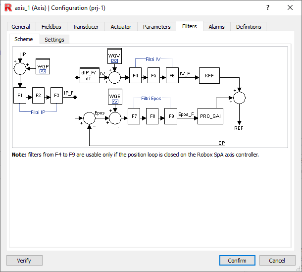
Up to 3 parallel filters can be added on the generation of the Ideal Position (IP), three for the Ideal Velocity (IV) and three for the position error (EPOS)
It is also possible to add three wave generators (see below) to analyze the behaviour of the mechanics.
The filters configuration is made in project configurator-->configuration-->axes-->filters
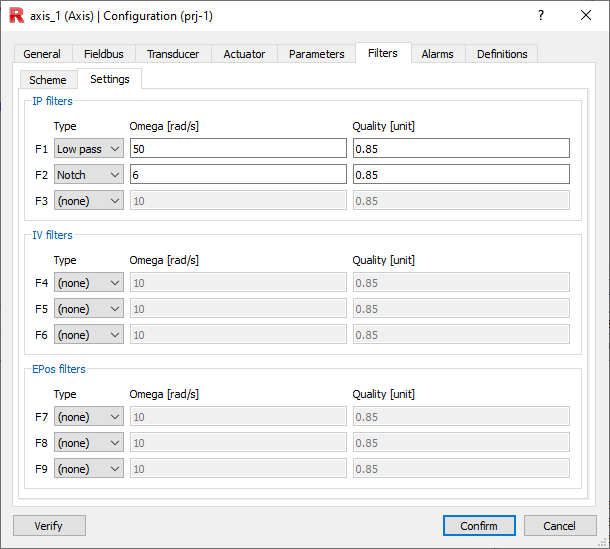
Types of filters
Filters that can be used |
Type |
Parameters |
Description |
|---|---|---|---|
Filters on the generation of the IP (Ideal Position) •F1_TYPE (first filter) •F2_TYPE (second filter) •F3_TYPE (third filter) |
0 disabled 1 notch 2 lowpass
|
Omega [rad/sec] -> frequency * DUEPI •F1_OMEGA •F2_OMEGA •F3_OMEGA The value is limited to 15% of the rule frequency * DUEPI |
In the variable IP_F the ideal (possibly) filtered position is computed. If no filter is imposed on IP, it is inferred that IP_F = IP. IV is computed as follows: •If IP has not been filtered the IV is calculated canonically, i.e., IVt = (IPt -IP t-1) / SI •If IP has been filtered (so IP <> IP_F) the reference IV is recalculated using IP_F, i.e. IVt = (IP_Ft -IP_F t-1) / SI RTE provides a circular buffer containing the IP_Fs computed in the previous 32 samplings. For access, use the function P_IP_F(ax,idx). NOTE: Filters on IP (F1-:-F3) are always valid regardless of who is doing the position ring closure. |
Quality Factor [unit] •F1_Q •F2_Q •F3_Q Value is limited to be no smaller than 0.75 for lowpasses and 0.2 for notches |
|||
Filters on IV (Ideal Velocity) generation. •F4_TYPE (first filter) •F5_TYPE (second filter) •F6_TYPE (third filter) |
0 disabled 1 notch 2 lowpass
|
Omega [rad/sec] -> frequency * DUEPI •F4_OMEGA •F5_OMEGA •F6_OMEGA The value is limited to 15% of the rule frequency * DUEPI |
The ideal (possibly) filtered speed is computed in the variable IV_F. If no filter is imposed on IV it is inferred that IV_F = IV The value of IV_F is then used in the automatic calculation of the speed reference: •SREF(ax) = ......+ IV_F(ax) * K_FF (ax) RTE provides a circular buffer containing the IV_Fs computed in the previous 32 samplings. Use the function P_IV_F(ax,idx) for access . NOTE: Filters on speed (F3-:F6) are usable only if the control generates a speed reference. |
Quality Factor [unit] •F4_Q •F5_Q •F6_Q Value is limited to be no smaller than 0.75 for lowpasses and 0.2 for notches |
|||
Filters on EPOS (Position Error). •F7_TYPE (first filter) •F8_TYPE (second filter) •F9_TYPE (third filter)
|
0 disabled 1 notch 2 lowpass |
Omega [rad/sec] -> frequency * DUEPI •F7_OMEGA •F8_OMEGA •F9_OMEGA The value is limited to 15% of the rule frequency * DUEPI |
The filtered (possibly) position error is computed in the variable EPOS_F. If no filter is imposed on EPOS, it is inferred that EPOS_F =EPOS. The value of EPOS_F is used in the automatic calculation of the velocity reference: •SREF(ax) = EPOS_F(ax) * PRO_GAI(Ax) + ...... NOTE: The filters on the error (F7-:-F9) are usable only if the control generates a speed reference. |
Quality Factor [unit] •F7_Q •F8_Q •F9_Q Value is limited to be no smaller than 0.75 for lowpasses and 0.2 for notches |
NOTA: EPOS(ax) = P_IP_F(ax, idx) - CP(ax)
NOTA: SREF(ax) = EPOS_F(ax) * PRO_GAI(Ax) + IV_F(ax) * K_FF (ax)
Types of wave generator
To enable the programmer to better analyze and optimize filter parameters RTE offers a sine, triangle or square wave generator on the specified axis.
NOTE: By enabling wave generators their effect is detectable on EPOS_F, IP_F and IV_F p respectively (even if no filter is applied).
Using the generator on IP has the side effect that using the ideal axis velocity is equivalent to having a filter on IP.
Wave generator over IP
Set WGP_TYPE as follows:
•0 off
•1 sinusoidal
•2 triangle
•3 square wave
Set WGP_FREQ wave frequency for IP [hz].
Set WGP_AMP value in units of IP wave amplitude [axis unit] .
Activate the previous settings on the desired axis: WGP_ON_AX axis on which to generate the wave.
NOTE: In the WGP_OUT variable, the value in IP units of the output value due to wave generation can be observed. [axis unit]
Wave generator on IV
Set WGV_TYPE as follows:
•0 off
•1 sinusoidal
•2 triangle
•3 square wave
Set WGV_FREQ frequency of the wave by IV [hz].
Set WGV_AMP value in units of IV wave amplitude [axis unit/sec].
Activate the previous settings on the desired axis: WGV_ON_AX axis on which to generate the wave.
NOTE: In the WGV_OUT variable, the value in IP units of the output value due to wave generation can be observed. [axis unit/sec]
Wave generator on EPOS (Position error).
Set WGE_TYPE as follows:
•0 off
•1 sinusoidal
•2 triangle
•3 square wave
Set WGE_FREQ wave frequency for IV [hz].
Set WGE_AMP value in units of IV wave amplitude [axis unit] .
Activate the previous settings on the desired axis: WGE_ON_AX axis on which to generate the wave.
NOTE: In the variable WGE_OUT you can observe the value in IP units of the output value due to wave generation. [axis unit]