Introduction
Enables interfacing of the motion controller typically to a PLC in a DeviceNet network.
Note: If used for DeviceNet communication, the controller cannot also be used as a canOpen or canbus intermodule(RBXCNET) master.
The Robox system can manage up to 32 devices with maximum data exchange of 64 bytes per device (at most 32 bytes read and 32 bytes write) and a maximum of 512 bytes for all devices in the network.
You can communicate with Robox controls in DeviceNet mode as follows:
•In RBXM controls using the CAN/PROF INT communication board (AS5034.010)
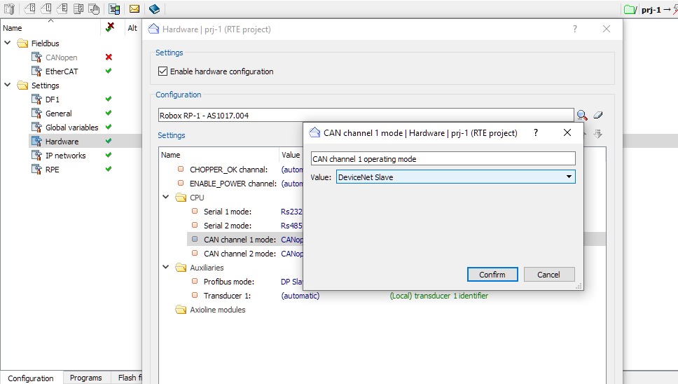
•In the uRmc2/uRmc3/RP1/RP2 controls such communication can be done using one of the two available CAN channels
The Robox control will appear as a MASTER or SLAVE type peripheral within the DeviceNet protocol.
Bookmarks
Slave functioning
To configure the Robox control as a DeviceNet slave, the file DNSn.CFG (n is the index of the board (0 -:- 7)) must be loaded into flash. The file must reside on flash in the CAN_DIR or FB_DIR directories. The Robox control will appear as a slave type device within the DeviceNet protocol.
The data structure within the individual block must be defined (on the Robox control) in the DNSn.CFG file.
Data interchange is done by using up to 2 blocks in reading and up to 2 blocks in writing.
The maximum length of the single block is 200 bytes.
The entities that can be defined in a write block (from outside to Robox) are as follows:
•Prefixed integer registers
•Real prefixed registers (in FLOAT or DOUBLE format)
•String registers
•Write semaphores (both integer and float and double sizes)
•Reserved zones
Entities that can be defined in a read block (from Robox outward) are as follows:
•Prefixed integer registers
•Real prefixed registers (in FLOAT * or DOUBLE format)
•String registers
•Input word
•Output word
•Reserved zones
NOTE: The master reads and writes to the CAN.INT channel at its working frequency. The control will provide data at the rule execution frequency.
NOTE: Remember that the format of float numbers is 4 bytes (1 of exponent and 3 of mantissa). The format of real numbers processed by the R3 language is 8 bytes (2 of exponent and 6 of mantissa). If, in the transformation of DOUBLE registers to FLOAT, the contents of the registers are greater than the numeric maximum that can be represented in float, this limit is taken as the value (with the right sign) (the value is 3.40282e38) (see IEEE standard 854).
NOTE: In case warm_rst.8 is active, all DeviceNet slave communications are disabled. Instead, DeviceNet master continues to operate normally.
Related arguments slave
Slave configuration for RBXM controls
To enable this communication, you must have the Robox CAN.INT communication board and the following files must be present on system flash device:
PFLMvvrr.O86 |
Loader for CAN cpu. vvrr are the 4 digits of version and revision |
DNESvvrr.O86 |
Executor for DeviceNet slave communication. vvrr are the 4 digits of version and revision |
Interchanged block structure definition file relative to the "nth" board in the rack. n is index of the CAN.INT boards involved; index 0 is relative to the first CAN board in the rack from the left, regardless of position within the rack |
Finding at switch on, a CAN/PROF.INT board (AS5034.010) configured DeviceNet slave, RTE attempts to load the corresponding management software PFLMvvrr.O86 and DNESvvrr.O86 within the SYS_DIR directory.
In case of absence or error while loading either file, alarm 9202 is generated.
Slave configuration for uRMC2, uRMC3, RP0, RP1, RP2 controls
To enable this communication, the DeviceNet use of the channel must be defined in the RHW.cfg file.
In addition, the following file must be present on system flash device (CAN_DIR or FB_DIR directory):
Interchanged block structure definition file related to CAN channel n+1 (e.g., DNS0.CFG is the configuration file of CAN channel 1) |
If an anomaly is found during analysis, an alarm is generated (see DeviceNet alarms) and there is warning in the report.
After running the rules the data exchange is then handled with the following structure:
•Read diagnostic area from CAN.INT board and copy data, if specified, to integer registers
•Verifying that the CAN.INT board is operational, otherwisealarm 9203 is generated
•Update data to CAN.INT board (only if data previously written by RBX CPU has been assumed by CAN.INT) (RBX --> DN)
•Update data from CAN.INT board if new information has been received (DN-->RBX). The data is recognized considering the possible semaphores
Master functioning
Since RTE 34.27.5, DeviceNet Master communication management has been added on controls with integrated CAN channel(s).
To configure the Robox control as a DeviceNet master, the file DNMSTn.cfg (n is the index of board 0 or 1) must be uploaded to flash. The file must be on flash in the CAN_DIR or FB_DIR directories. The Robox control will appear as a master type device within the DeviceNet protocol.
The data structure within the individual block must be defined (on the Robox control) in the DNMSTn.cfg file.
The entities that can be defined in a block in writing (from outside to Robox) and reading (from Robox outward) are as follows:
•Prefixed integer registers
•Real prefixed registers (in FLOAT or DOUBLE format)
•Reserved zones
Related arguments master
Master configuration for uRMC2, uRMC3, RP0, RP1, RP2 controls
To enable this communication, it is necessary to manually define in the RHW.cfg file the DeviceNet usage as the CAN port operating mode by entering the keyword "Dev_Net_M." For example if you want to use port 1 you have to write:
; ... [MCPU] ; {0:1} Slot definitions SLOT 0 CPURBX PSER 1 RS232 PSER 2 RS232 ETH 1 ETH 2 ETH 3 CAN 1 Dev_Net_M ; ... |
In addition, the following file must be present on system flash device (CAN_DIR or FB_DIR directory):
Interchanged block structure definition file related to CAN channel n+1 (e.g., DNMST0.CFG is the configuration file of CAN channel 1) |
If an anomaly is found during analysis, an alarm is generated (see DeviceNet alarms) and there is warning in the report.
After running the rules the data exchange is actually handled with the following structure:
•Read diagnostic area from CAN.INT board and copy data, if specified, to integer registers
•Verifying that the CAN.INT board is operational, otherwise alarm 9203 is generated
•Update data to CAN.INT board (only if data previously written by RBX CPU has been assumed by CAN.INT) (RBX --> DN)
•Update data from CAN.INT board if new information has been received (DN-->RBX)
NOTE: For some controls you could also communicate without having to enter task and rule. In this way, for example on RP-2, you would obviously no longer communicate in execution mode but in programming mode.
DeviceNET Alarms
|
|
Keywords DeviceNET
sys_flag.20 (0x100000) |
Enable entry into the report of information regarding communication |
|
|
sys_flag_2.3 (0x0008) |
Enable entry into the report of information regarding DeviceNet Master configuration |
sys_flag_2.4 (0x0010) |
Enable entry into the report of information regarding the sending of DeviceNet messages (for the time of SYS_COUNT) |
sys_flag_2.5 (0x0020) |
Enable entry into the report of information regarding receiving DeviceNet messages (for the time of SYS_COUNT) |
sys_flag_2.6 (0x0040) |
Disable the generation of the alarm 9241 |
sys_flag_2.7 (0x0080) |
Disables the generation of the alarm 9242 |
sys_flag_2.8 (0x0100) |
Disables the generation of the alarm 9243 |
sys_flag_2.9 (0x0200) |
Disables the generation of the alarm 9203 |
|
|
Mask of configured master fieldbus channels |
|
Mask of configured slave fieldbus channels |