This page contains the steps used to create the basis of each RDE project. Also are described some basic concepts to know in order to use the RDE development environment.
Creating the project configurator
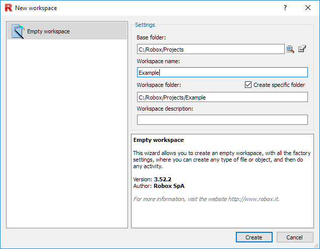
Workspace -> New Workspace... choose directory and name.
Workspace -> New Object... choose RTE Project and its name.
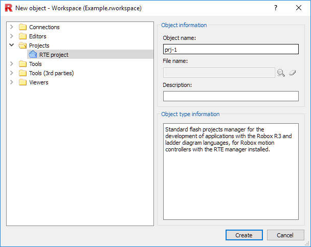
Once Create is pressed, the project configurator window will automatically open.
Connection with the device
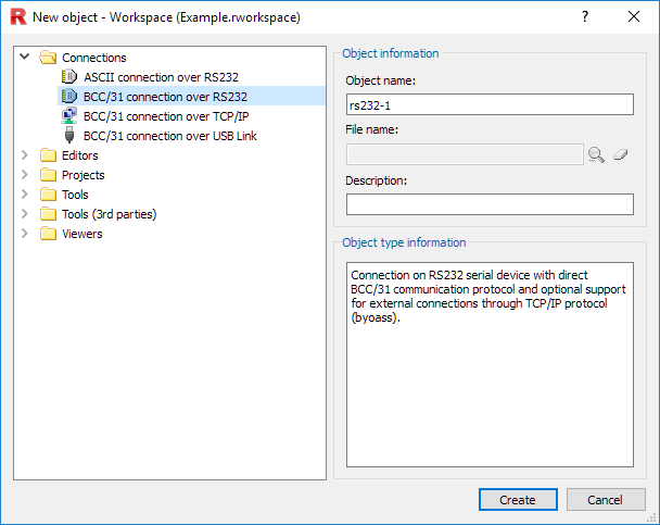
Once you have created the project configurator, in order to communicate with the device you must create a connection through Workspace -> New Object... -> Connections.
Then select the type of connection you are using (serial, Ethernet or USB) and choose the name of the connection.
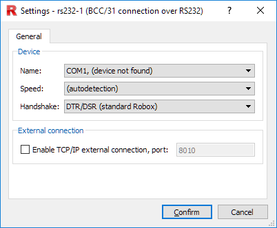
Serial connection
Selecting serial communication will open the relevant window, where the serial port of the PC being used, the baud rate of communication, and the type of handshake must be set.
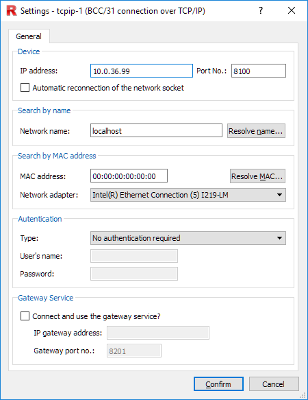
Ethernet connection
Selecting Ethernet communication will open the relevant window, where the IP address of the device should be set.
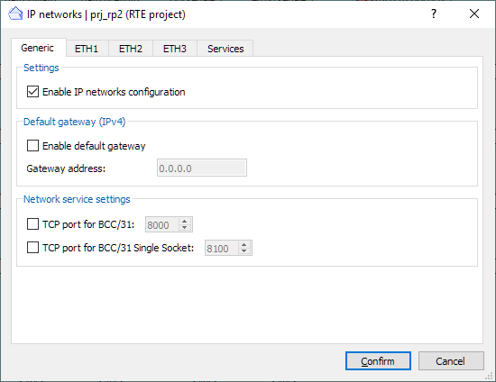
You must then create the network configuration for the device.
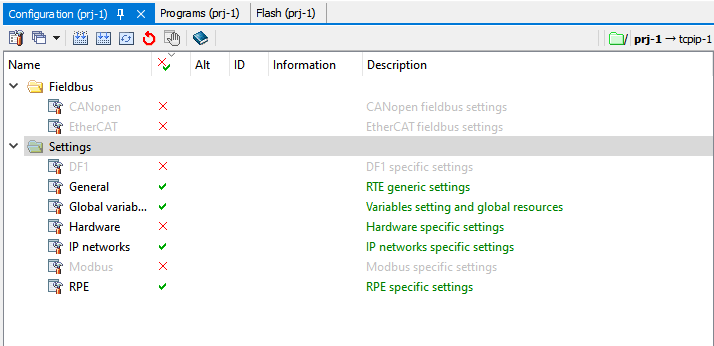
From the project configurator, press on the properties icon (the first on the top left) -> Configuration. Make sure you have enabled the generation of the IP Networks configuration file.
From project configurator -> Configuration press on IP Networks, enable network configuration and set IP address and net mask of the Ethernet port used to communicate with the PC.
Select the project configurator window, Edit (or right click on the window) -> Generate -> IP networks configuration only.
This will create the file IPADDR.DEF (or NETWORK.CFG if advanced configuration is enabled). This file contains the information of the IP Networks used by the device and must be placed inside the Compact Flash (or SD) through a Make or Rebuild operation.
USB Connection
Selecting USB communication will open the referred window where the devices connected via USB are displayed, with their Part Number and Serial Number.
NOTE: There may be a need to update the drivers if the device is not recognized. Follow the procedure described in the control manual to update the drivers.
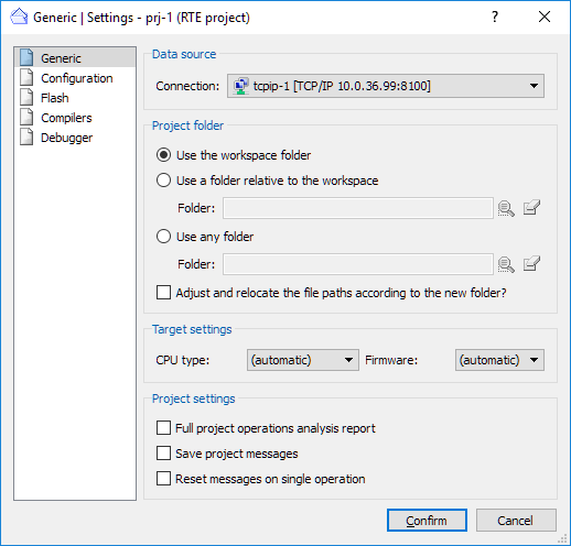
Project connection link
Once the connection has been chosen, from the project configurator press on the properties icon (the first on the top left) -> General, then select the connection used to communicate with the device.
NOTE: The connection used to communicate with the device must be set with each new object that is created (variable monitor, oscilloscope, command shell...) and is always done by pressing on the properties icon. You can also link directly to the project, so the connection used by the object will be the same as the one used by the project configurator.
Creating the command shell
The Shell is a tool provided by RDE, used to send commands to the connected Robox device.
To create a shell, select Workspace -> New Object... -> Tools -> Command Shell.
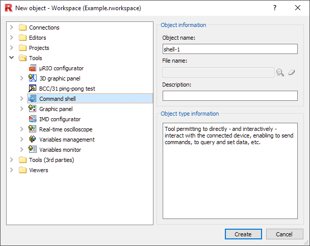
Then select the shell you just created and press on the properties icon (the first on the top left) -> General, then select the connection used to communicate with the device (or link directly to the project connection).
Having arrived at this point you have a basic RDE project, with a connection to the control being used and the possibility of sending device/shell commands to it.
Notes
In the same way as the shell just created, it is possible to use additional tools within the project that may be useful for the project, such as oscilloscopes, variable monitors, graphic panels, ...
For a description of the settings provided by the project configurator, see RTE: configuration.
To understand the program management done by RTE, see RTE: programs.
To understand axis configuration management, see: RTE: axis configuration.
To understand flash file management done by RTE, see RTE: flash files.