The preset cycle is performed when the machine is installed the first time. Subsequently it can be performed at the operator's request.
These machines usually install multi-turn absolute transducers.
Sometimes the position retentivity is required also in machines not equipped with absolute transducers (for instance because they cannot move if the electrical cabinet is off, or they install parking brakes)
The transducer must be configured as follows:
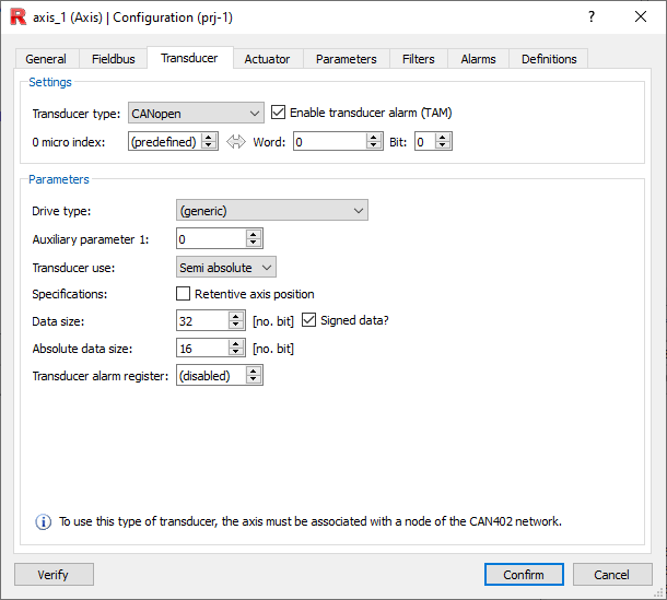
Transducer type
The choice between CANOpen, EtherCAT (CoE), EtherCAT (SoE) is made according to the type of fieldbus used.
Micro zero index
If the drive used does NOT appear in the drive type selection list you must specify here the address of the digital input channel where the micro or prox is physically wired to perform axis zeroing.
Function MVA_ZC may be used but full precision cannot be programmed.
NOTE: The POS_CAPTURE_CMD instruction is not handled.
If the drive is present in the drive type selection dropdown, it is possible:
•Specify the input where the micro or prox is physically wired
•Leave (default) and indicate in auxiliary parameter 1 related to drive type where the input is wired to the drive
Function MVA_ZC may be used with full precision programming as well.
NOTE: Instruction POS_CAPTURE_CMD is handled.
To have retentive quota handling, it is necessary to put the FLAG on retentive axis position and specify the characteristics of the quota information coming to RTE.
This information depends, of course, on the type of transducer and any processing done by the drive.
Examples of transducer usage:
Transducer |
Transducer usage |
data size |
absolute data |
|---|---|---|---|
Encoder |
incremental |
32 |
- |
Encoder |
semi-absolute |
32 |
0 |
12 Bit Resolver |
semi absolute |
32 |
12 |
16 Bit resolver |
semi absolute |
32 |
16 |
Endat eqi1130 |
semi absolute |
32 |
30 |
Trasd_27 |
semi absolute |
32 |
32 |
Trasd_27 |
absolute |
32 |
- |
NOTE: Note the equivalence between use of transducer (encoder) configured incremental or semi absolute (32, 0).
NOTE: Note also the equivalence between use of transducer(Trasd_27) configured absolute or semi-absolute (32, 32).
RTE, having the above information available, performs the following handling:
•The predefined variable c0_done becomes retentive
•The unwrapping of the incoming information from the transducer is handled
•Saves the axis quota at power-off and resets it, possibly modified, at the next restart
•Performs at switch on a check on the read position and the saved position
•Manages the offset between the absolute quotas of the drive world and the control world
as follows:
At switch on RTE, if c0_done true and FLAG quota retentivity active, imposes the real quota stored at switch on, modified by the detected variation between the RAWCP stored at switch on and the one detected at switch on.
NOTE: From RTE 34.11.6, even in case of C0_DONE = 0, retentive quotas are imposed. Through SYS_CFG.3 it is possible to avoid such handling.
If the absolute value of the change is greater than the MAX_D_RAW parameter, the alarm is generated: "40#nAx Retentive Transducer : max movem. exceeed.
The default MAX_D_RAW parameter is equal to one-fourth the number of bits of the absolute component.
By how much can the quota vary while RTE is off?
It obviously depends on how many bits the absolute information of the transducer is.
If a two-pole resolver is used that returns the absolute position of the crankshaft in the 12-bit revolution then the crankshaft will be able to move a maximum of a quarter turn clockwise and a quarter turn counterclockwise before alarm 40 is generated.
NOTE: RTE can never notice movements that exceed what the absolute data bit can represent. Such checking is done by RTE within the limits of the information given by the transducer!
Equal control is done, for example, in the case of 30-bit absolute part multiturn transducer. In this case the MAX_D_RAW threshold is initialized to 2^28 bits (1/4 of the absolute data size).
It is also obvious that in the case of multiturn absolute transducers, since the absolute data has a larger number of bits, the MAX_D_RAW parameter is much larger and therefore much larger will be the allowable displacement of the axes when the control is stopped.
If, for example, a multiturn transducer with 30 bits of absolute data is used (18 in the turn and 12 of turns), the number of turns that can be made when the control is off before alarm 40 is generated will be (2^30/2^18)/4 = 1024.
The variable MAX_D_RAW can still be initialized by the user to the desired value.
It will have to be handled by the application software in accordance with the predefined variable C0_DONE whether or not the home cycle is executed.
Transducer alarm register
Disabled (however indifferent).