Allows to define the type of position transducer for the specified axis.
Syntax |
TRD n xxxxxx [-EA] [-0Mnn] [-REPn] |
|---|---|
n |
Number of axis (1÷32) |
xxxxxx |
Transducer type. Each of the following items may have additional parameters, so you should consult their documentation before use. •OFF •ABS •CAN •NVR •R •NVRR •RR •COE •SOE |
EA |
If present enables transducer alarm (optional) |
0Mnn |
Specifies the channel of the zero micro. If 0 the transducer one is used (optional) |
REPn |
Repeats transducer definition by incrementing axis number and any indices n times (1÷32) (optional) |
Notes |
Diagnostics are issued for double axis definition or unknown xxxxxx code |
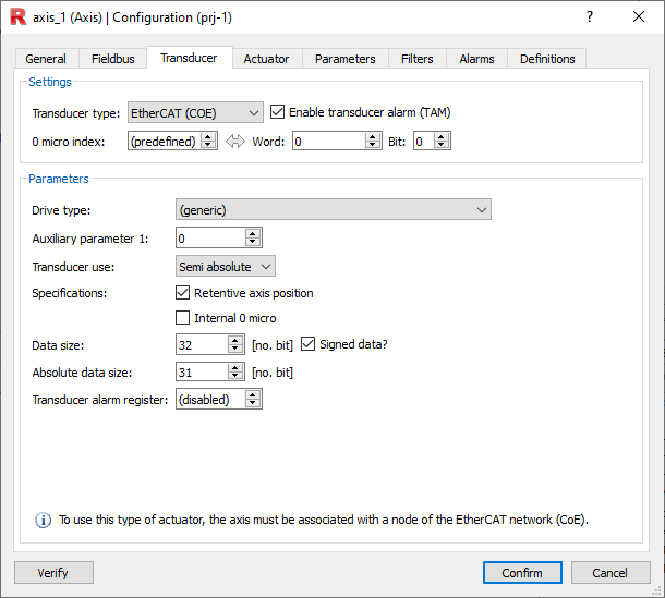
WARNING: This keyword is automatically generated by project configurator.
Project Configurator --> Axis --> Transducer
NOTE: For more information regarding the parameters to be set, press here.
Allowed device types (ttt)
OFF (axis without position reference)
Syntax |
OFF |
|---|---|
Notes |
Diagnostics are issued for double axis definition or unknown ttt code |
Example
TRD 21 OFF |
ENC_INC (Axis with incremental encoder transducer)
Syntax |
ENC_INC en -RIT |
|---|---|
en |
Encoder channel number (1÷32) |
RIT |
If present enables CP storage management in retentive ram. (optional, default disabled) |
Notes |
Diagnostics are issued for double axis definition or unknown ttt code |
Example
TRD 1 ENC_INC 2 -RIT -EA -0M151 |
ABS (Axis with absolute encoder transducer)
Syntax |
ABS en -Bnbit -Ffreq SEMIABS -Ooffset |
|---|---|
en |
SSI channel number (1÷32) |
nbit |
Output device bit number (1÷32) and mode of use (if negative is assumed signed, if positive unsigned) (optional, default -24) |
freq |
Working frequency in KHz. (optional, default 100) |
SEMIABS |
If present indicates that the SSI quota is to be used in semi absolute mode (optional, default is absent -> absolute mode) |
Ooffset |
Offset value to be removed from the SSI value (optional) |
Example
TRD 1 ABS 3 -B-24 -F100 SEMIABS -O2 -EA -0M151 |
INP_ANALOGIC (Axis with analog input transducer)
Syntax |
INP_ANALOGIC ia -Bnbit -MINminvalue -MAXmaxvalue -Offset |
|---|---|
ia |
Analog input channel number (1÷32) |
nbit |
Output device bit number (1÷32) and mode of use (if negative is assumed signed, if positive unsigned) |
minvalue |
Minimum value below which alarm is generated (optional, default -2048) |
maxvalue |
Maximum value above which alarm is generated (optional, default 2048) |
offset |
Offset value to be removed from the read value (optional) |
Notes |
Diagnostics are issued in case of out-of-range parameters |
Example
TRD 1 INP_ANALOGIC 4 -B-12 -O5 -MIN0 -MAX10 -EA -0M151 |
CAN (axis referenced via CANOPEN)
Syntax |
CAN -Ddrive -AUXpar -Bnbit -RIT MODE -ALn |
|---|---|
drive |
Indicates the type of drive selected (default 0 -> generic drive) |
par |
Specifies the index of the auxiliary parameter The value of the auxiliary parameter is imposed according to the type of drive used |
nbit |
Output device bit number (1÷32) and usage mode (if negative is assumed signed, if positive unsigned) |
RIT |
If present enables real quota storage management in retentive ram. (optional, default disabled) |
MODE |
Indicates the mode in which the transducer is being used: •ABS: if the transducer is absolute •INC: if the transducer is incremental •SEMI nn: if the transducer is semi-absolute. "nn" indicates the size of the absolute data |
n |
Index of an R register to be used as a flag for transducer alarm generation. If the register is imposed other than 0 I will generate the alarm. (optional) |
Notes |
This definition is accepted only if the axis has been previously defined as axis can |
Example
TRD 1 CAN -D0 -AUX5 -B-32 -RIT SEMI 16 -AL3 -EA -0M151 |
R (axis with transducer on integer register R)
NVR (axis with transducer on NVR integer register)
Syntax |
R idx -Bnbit ABS -ALn NVR idx -Bnbit ABS -ALn |
|---|---|
idx |
|
nbit |
Output device bit number (1÷32) and usage mode (if negative is assumed signed, if positive unsigned) (optional, default 32) |
ABS |
If present indicates to use the register value as absolute position. (optional, default not present -> incremental) |
n |
Index of an R register to be used as a flag for transducer alarm generation. If the register is imposed other than 0 I will generate the alarm. (optional) |
Notes |
Diagnostics are output for out-of-range parameters |
Example
TRD 1 R 3 -B-32 -RIT -AL4 -EA -0M151 TRD 1 NVR 3 -B-32 -RIT ABS -AL4 -EA -0M151 |
RR (axis with transducer on real RR register)
NVRR (axis with reference on real register NVRR)
Syntax |
RR idx INC -ALn NVRR idx INC -ALn |
|---|---|
idx |
|
INC |
If present indicates to use register value as incremental position (optional, default not present -> absolute) |
ALn |
Index of an R register to be used as a flag for transducer alarm generation. If the register is imposed other than 0 I will generate the alarm. (optional) |
Notes |
Diagnostics are output for out-of-range parameters |
Example
TRD 1 RR 2 -RIT INC -AL4 -EA -0M151 TRD 1 NVRR 3 -RIT -AL5 -EA -0M151 |
COE (axis referenced via Canopen over EtherCAT)
Syntax |
COE -Ddrive -AUXpar -Bnbit -RIT -IU0 MODE -ALn |
|---|---|
drive |
Indicates the type of drive selected (default 0 -> generic drive) |
par |
Specifies the index of the auxiliary parameter The value of the auxiliary parameter is imposed based on the type of drive used |
nbit |
Output device bit number (1÷32) and usage mode (if negative is assumed signed, if positive unsigned) |
RIT |
If present enables real quota storage management in retentive ram. (optional, default disabled) |
-IU0 |
If present indicates use of internal u0. |
MODE |
Indicates the mode in which the transducer is being used: •ABS: if the transducer is absolute •INC: if the transducer is incremental •SEMI nn: if the transducer is semi-absolute. "nn" indicates the size of the absolute data |
n |
Index of an R register to be used as a flag for transducer alarm generation. If the register is imposed other than 0 I will generate the alarm. (optional) |
Notes |
This definition is accepted only if the axis has been previously defined as an EtherCAT network (CoE) node |
NOTE: From the EtherCAT Communication page you can access links regarding methods to configure various drives via CoE.
Example
TRD 1 COE -D0 -AUX5 -B-32 -RIT ABS -EA -0M151 TRD 1 COE -D0 -AUX5 -B-32 -RIT -IU0 SEMI 16 -AL2 -EA -0M151 |
SOE (axis referenced via Servodrive over EtherCAT)
Syntax |
COE -Ddrive -AUXpar -Bnbit -RIT MODE -ALn |
|---|---|
drive |
Indicates the type of drive selected (default 0 -> generic drive) |
par |
Specifies the index of the auxiliary parameter The value of the auxiliary parameter is imposed based on the type of drive used |
nbit |
Output device bit number (1÷32) and usage mode (if negative is assumed signed, if positive unsigned) |
RIT |
If present enables real quota storage management in retentive ram. (optional, default disabled) |
MODE |
Indicates the mode in which the transducer is being used: •ABS: if the transducer is absolute •INC: if the transducer is incremental •SEMI nn: if the transducer is semi-absolute. "nn" indicates the size of the absolute data |
n |
Index of an R register to be used as a flag for transducer alarm generation. If the register is imposed other than 0 I will generate the alarm. (optional) |
Notes |
This definition is accepted only if the axis has been previously defined as an EtherCAT network node (SoE) |
Example
TRD 1 SOE -D0 -AUX1 -B-32 -RIT ABS -EA -0M151 TRD 1 SOE -D0 -AUX0 -B-32 SEMI 16 -AL2 -EA -0M151 |