The following explains how to configure "Position Capture" depending on the EtherCAT (COE) drive used. Depending on the type of driver, the CANopen objects to be used are different.
Once the "Drive Type" is selected in the Transducer window of the axis configuration screen, the necessary CANopen objects will be displayed in the Field Bus--> Connections window under Auxiliary Resources.
Bookmarks
Generic Drive
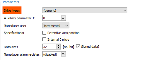
"Generic" drivers means all those that are not listed in the "Drive Type" field. For these drivers you have to select "(generic)":
A drive that supports "Position capture" handles the following objects:
Objects |
Meaning |
M = Mandatory / O = Optional |
|---|---|---|
60B8:0 |
Touch probe function (access in r/w) |
M |
60B9:0 |
Touch probe status |
M |
60BA:0 |
Touch probe 1 positive edge |
O |
60B3:0 |
Touch probe 1 negative edge |
O |
60D0:1 |
Touch probe source |
- |
60D5:0 |
Touch probe 1 positive edge counter (only for continuous capture) |
M |
60D6:0 |
Touch probe 1 negative edge counter (only for continuous capture) |
M |
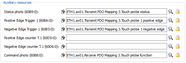
"Touch probe status" 0x60B9 and "Touch probe function" 0x60B8 objects must be mapped to the cyclic PDOs.
The objects should be mapped in the axis configuration screen--> Field Bus--> Links:
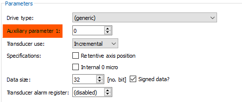
When defining the transducer configuration, the field "Auxiliary Parameter 1" can take the following values (Axis Configuration Screen--> Transducer):
Values |
Description |
|---|---|
0 |
captures only on ch0 |
1 |
uses input 1 of the drive as touch probe input |
2 |
uses input 2 of the drive (if available) as touch probe input |
3 |
uses input 3 of the drive (if available) as touch probe input |
4 |
uses input 4 of the drive (if available) as touch probe input |
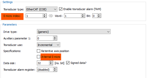
The "0 Micro Index" field corresponding to the specified "Auxiliary Parameter 1" field must also be configured, and the "Internal 0 Micro" flag must be set (Axis Configuration Screen--> Transducer):
Robox RID20 Drive
In the axis configuration screen--> Transducer--> Drive type, select "Robox RID20E".
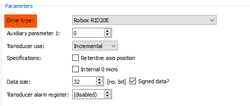
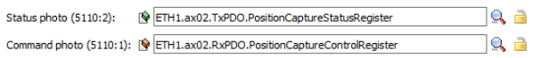
The objects "Status photo" 0x5110:2 and "Command photo" 0x5110:1 must be mapped in the PDOs: axis configuration screen--> Field Bus--> Links.
Drive Robox IMD
In the axis configuration screen--> Transducer--> Drive type, select "Robox IMD20".
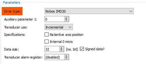
The objects "Status photo" 0x5110:2 and "Command photo" 0x5110:1 must be mapped in the PDOs: axis configuration screen--> Field Bus--> Links.
Nidec Digitax M753 Drives
NIDEC drives have the peculiarity that they do not allow the configuration parameters of the standard COE function of Touch Probe to be changed when the axis is enabled, and they do not independently manage the transducer "channel of 0" signal source.
This peculiarity mainly affects 2 functions of the RTE:
•MVA_ZC which performs the axis zero cycle in case the "full precision" mode is requested (zcFlag.2)
•the function of POS_CAPTURE
NOTE: Always use 0 as the index of the micro.
To use the Touch Probe (on Homing and Pos_capture) with NIDEC drives, the following steps should be taken.
In the axis configuration screen--> Transducer--> Drive type, select "Nidec M753":
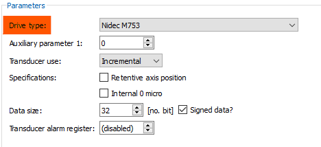
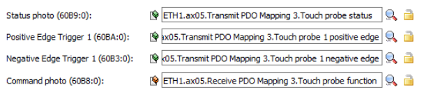
The objects "Status photo" 0x60B9:0, "Command photo" 0x60B8:0, "Positive Edge Trigger 1" 0x60BA:0 and "Negative Edge Trigger 1" 0x60B3:0 must be mapped in the PDOs: axis configuration screen--> Field Bus--> Links.
In the transducer configuration definition, the field "Auxiliary Parameter 1" can take the values:
Value |
Description |
|||||||||||||||
|---|---|---|---|---|---|---|---|---|---|---|---|---|---|---|---|---|
0 |
•the micro (if required) must be connected to digital input 4 of the drive •full precision can be used only if the transducer has physical channel 0 connected to transducer 1 of the drive NOTE: To be in a condition to perform hardware position capture, the POS_CAPTURE function must be executed at least once before enabling the drive. |
|||||||||||||||
1 |
Drive position capture is selected via the 0x60D0:1 object. It should be set when drive is disabled.
|
|||||||||||||||
2 |
It has the same characteristics as value 1, but the content of object 0x60D0:1 is initialized by reading from the drive parameter 03.100 (F1 Freeze Trigger Source Value) |