The following explains how to configure "Position Capture" depending on the CANopen drive used. Depending on the type of driver, the CANopen objects to be used are different.
Generic drive
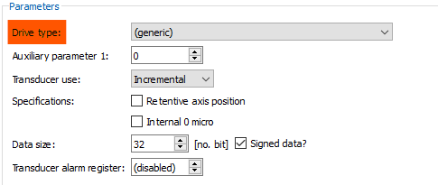
"Generic" drivers means all those that are not listed in the "Drive Type" field. For these drivers, "(generic)" must be selected:
A drive that supports "Position capture" handles the following objects:
Objects |
Meaning |
To be connected to |
M = Mandatory / O = Optional |
|---|---|---|---|
60B8:0 |
Touch probe function (with r/w access) |
Output 0 aux |
M |
60B9:0 |
Touch probe status |
Input 0 aux |
M |
60BA:0 |
Touch probe 1 positive edge |
Input 1 aux |
O |
60B3:0 |
Touch probe 1 negative edge |
Input 2 aux |
O |
60D0:1 |
Touch probe source |
- |
- |
60D5:0 |
Touch probe 1 positive edge counter (only for continuous capture) |
Input 3 aux |
M |
60D6:0 |
Touch probe 1 negative edge counter (only for continuous capture) |
Input 4 aux |
M |
"Touch probe status" 0x60B9 and "Touch probe function" 0x60B8 objects must be mapped to the cyclic PDOs.
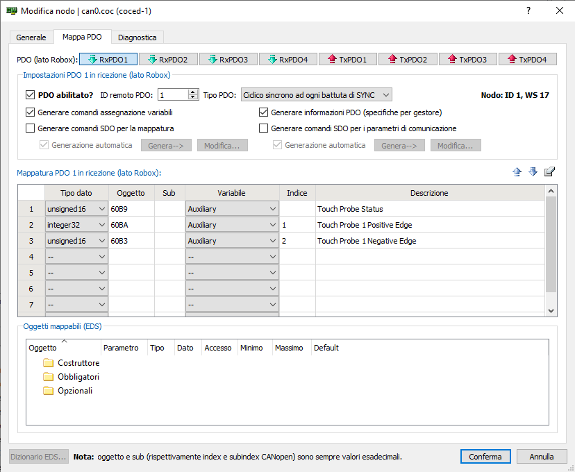
The mapping should be done according to the previous table in the CANopen editor, in the node configuration window.
Mapping example, objects 0x60B9, 0x60BA and 0x60B3 are mapped to RxPDO1:
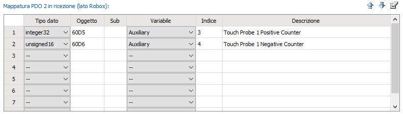
Objects 0x60D5 and 0x60D6 are mapped into RxPDO2:
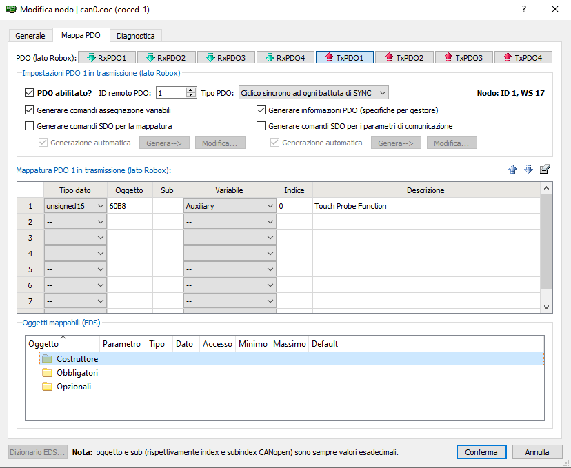
Object 0x60B8 is mapped into TxPDO1:
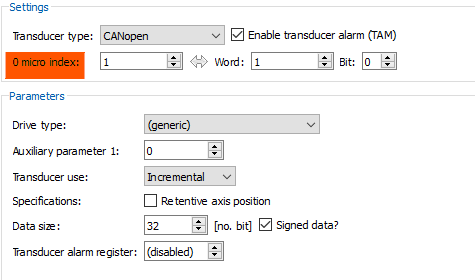
In the transducer configuration definition, the field "Auxiliary Parameter 1" can take the following values (Axis Configuration Screen--> Transducer):
Values |
Description |
|---|---|
0 |
captures only on ch0 |
1 |
uses input 1 of the drive as touch probe input |
2 |
uses input 2 of the drive (if available) as touch probe input |
3 |
uses input 3 of the drive (if available) as touch probe input |
4 |
uses input 4 of the drive (if available) as touch probe input |
The "0 Micro Index" field corresponding to the specified "Auxiliary Parameter 1" field must also be configured (Axis Configuration Screen--> Transducer):